Full size feeder initial setup and tests.
With our feeder our ultimate aim is not to have a RC radio link, just the radio link to the base station. With this strategy the issue arises of how to move the rover around when not on a mission. Others have previously highlighted this when using a larger vehicle that can’t be physically picked up.
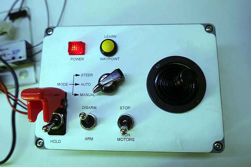
Our plan has been to build a local control panel on the rover to mimic an RC receiver. This would allow the rover to be driven around manually either walking beside it or sitting on it. If the initial trails are successful we will remove the remote RC radio and substitute this local control panel.
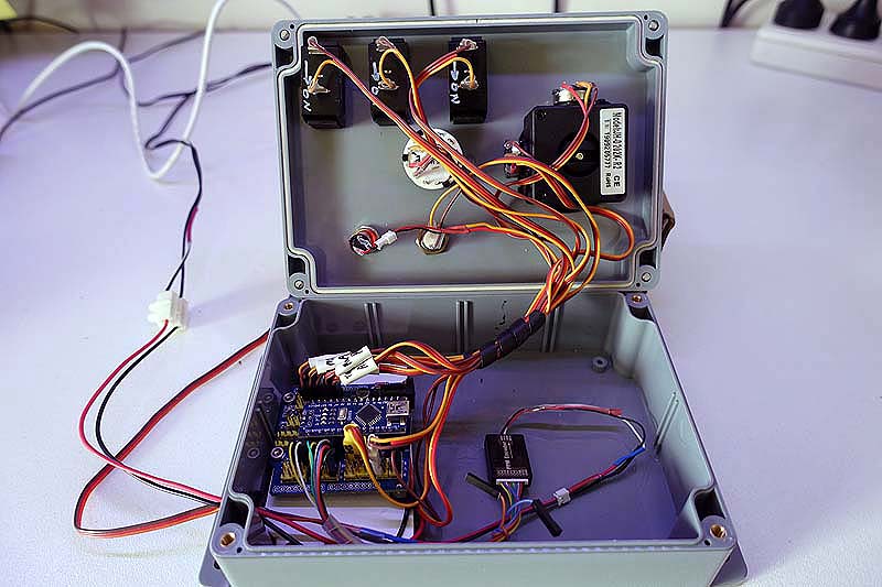
The one we have constructed has a joystick and a limited number of switches to provide the minimum functionality needed to drive the rover. An Arduino Uno is the brains doing the work.
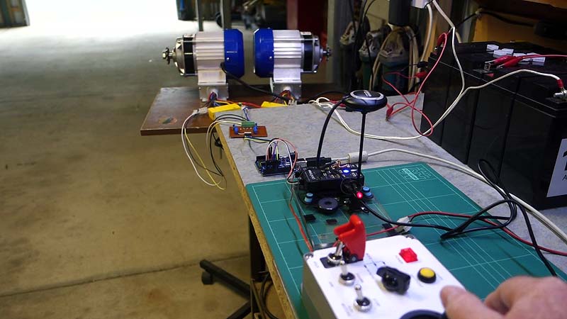
Our initial drive setup uses two ubiquitous 500W brushless motors and their controllers purchased off eBay. These controllers proved to be a nuisance in that the control signal required was an analogue voltage from 0.78v (stopped) to 3.05v (full speed) and with reverse achieved by switching a separate input wire. The other wrinkle was inbuilt maximum acceleration and deceleration rates. Visually these rates seemed a little slow but I was hopeful it wouldn’t give control problems others have experienced with slow actuators in their speed control systems.
To generate the required analogue voltage and reversing signal from the PWM control signal of the Pixhawk I used another Arduino Uno. Thus a PWM signal of 1000mSec generates a voltage of 3.05v and the reverse signal on, for 1500mSec the voltage was 0.78v and for 2000mSec the voltage is again 3.05v but the reverse signal is off. I included a small dead band at the centre to ensure the motors truly stopped.
On the bench this worked very well indeed.
The resultant drive system was installed with a test Pixhawk setup on our full sized feeder. Immediately obvious was that the top speed was too fast and so we reduced the control voltage range from 0.78-3.05v to the rather narrow 0.78-2.00v. With this range the top speed was about 1.5 metres/sec and despite the narrow voltage range the controllability was good.
Also immediately obvious was that the lack of strong engine braking from our brushless motor setup was a problem. Our hope that the brushless motors would remain in sync while slowing and provide the braking control was totally misplaced. If the speed was changed only gradually the motor controls functioned as designed and the rover drove well. However with sudden speed reductions the low rolling resistance combined with the relatively high weight of the rover meant that inertia quickly had the motors lose sync with their controllers. Control could only be re-established after the motors came to a complete stop.
Needless to say after a couple of heavy crashes into the retaining walls in my garden I came to the conclusion I had made a serious mistake.
We have decided to retreat to the more conventional brushed DC motors. These are now on order; TBC.
Stay safe.


