I am in the process of building an autonomous rover to carry out feeding on a crayfish farm.
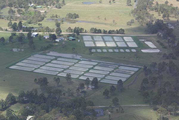
Redclaw are an Australian native freshwater crayfish that I farmed in southern Queensland for the last 20 years.
Farming is done in purpose built freshwater ponds normally about 50 metres by 20 metres.
Feeding is carried out several times per week. The feed is a pelletised grain mixture and distributed over the surface of the pond.
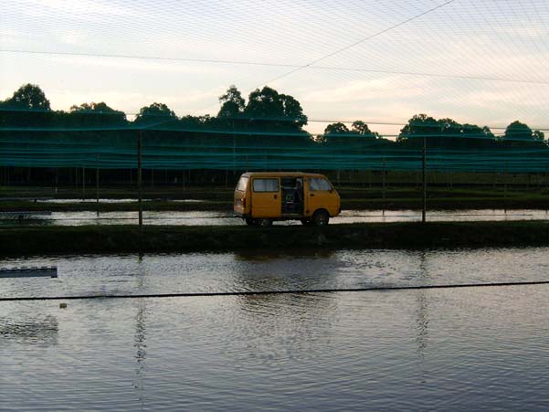
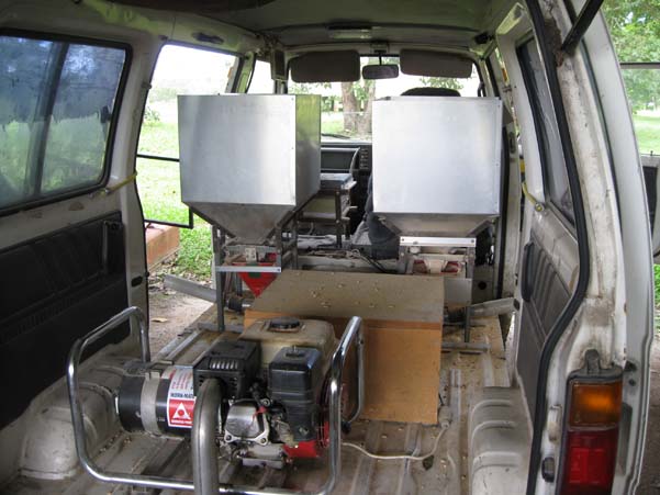
Over the years I developed a feeder inside a small delivery van which we drove around the ponds. A computer and metering system is used to control the quantity of pellets distributed to each pond. This varies depending on the level of stock in the ponds, stage of the growth cycle, etc.
A colleague in north Queensland while unashamedly stealing my design for his own feeder enthusiastically agreed with my suggestion that a fully autonomous feeder would be much more fun.
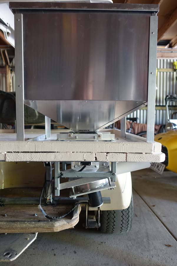
My colleague has changed the distribution mechanism from a blower arrangement to an electric spinner and has set up the feeder on the back of a golf buggy. A GPS has also been integrated to automatically start and stop the feeding sequences. The driver behind these changes was to prepare for an autonomous feeder.
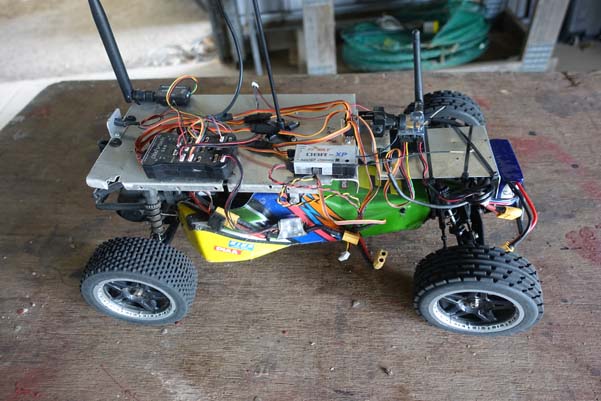
Being totally ignorant of autonomous vehicles our initial test was to temporarily fit a Pixhawk to one of my RC cars using cable ties and bits of string. Being amazed at what could be achieved so cheaply and simply gave us enough encouragement to push on - albeit very slowly.
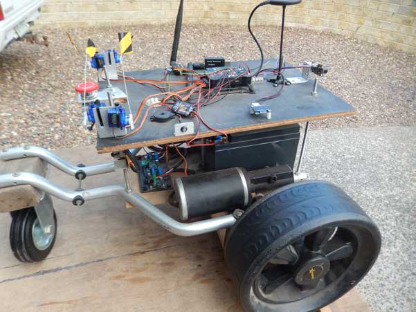
More recently we have purchased a small motorised golf bag carrier and modified it as our prototype. I have fitted a Pixhawk, Pololu Simple Motor controller 18V15 to control the motors, URM09 Analog Ultrasonic Sensor and 4 servos to allow simulation of the feeder motors. I have set up a Raspberry Pi as a companion computer but have not used it except for testing the Mavproxy communication.
I have managed to get this running OK within the limitations of the Ublox Neo-m8n GPS.
A rough video of an early successful test run on youtube:
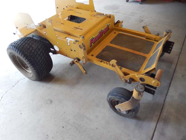
We have also purchased the wreck of a Hustler “Fastrack” zero turn mower. I have stripped it down to the bare chassis and am in the process of fitting a hybrid stepper motor/gearbox to each wheel.
At the North Queensland farm we have established a Polaris RTK GPS with our own base station and have integrated it into the existing feed distribution program.
A natural advantage we have is that it is very unlikely that people or animals will be inside the pond area. Secondly the feeding is not a critical activity that must be completed on time allowing us to just stop the feeder if anything goes amiss.
A big disadvantage is that any small navigation error will have the feeder underwater.
To be continued………………
Great progress! I’ve often thought that ArduPilot (Rover/Boat) would be good for providing feed on oyster farms so this is a bit similar.
Looking forward to hearing more about your progress and feel free to ping me if you hit issues. Also feel free to set the category to “Blog” on your next post so it appears on the front page of AP. Really great!
Thanks Randy, all and any words of encouragement are much appreciated.
We feel there are a number of aquaculture sectors (and some non-aquaculture) that would benefit from a similar approach and would dearly like to see our efforts be a catalyst for others.
I have added the latest trial run on youtube:
This is the last of my trial runs on the football field. I am shipping the prototype to the north Queensland farm and traveling up there mid-January. We will fit the RTK GPS and give it a run around the ponds - hopefully without getting it wet!
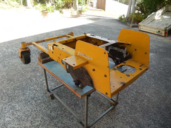
Meanwhile I have completed the deconstruction of our zero turn mower:
Hey bill, if you find yourself in need of some in-depth assistance from an ArduPilot developer who happens to also be based in Queensland( i’m normally Based in Brisbane), that’s me, so feel free to get in touch.
Your rover project looks looks about as finished as my current project… a lawn mower based on bits from a wheelchair. david / buzz. https://ardupilot.org/plane/docs/common-commercial-support.html
Hi David, thanks heaps for the contact. It is great to have an offer of assistance so close.
As you can see we are still experimenting with and learning the basics. However, we have much grander plans/dreams that will undoubtedly test us beyond our limits.
Our current plan is for me to take the converted zero turn mower to the NQ farm mid-April. It needs to be mobile and tested in a basic form by then - ie to the current stage of our prototype - which has me both nervous and excited. In the meantime the plan is for my NQ colleague to use the prototype to start with the development of the mission control software running on the companion computer and integrating the operation into his network.
It is when we get the zero turn to the farm and start to extend its capability that we may need help with the development. I would like to keep in close contact so that we can compare notes and build on our experiences.
After some unforeseen delays we finally got the prototype to the farm and successfully installed the RTK GPS to the rover.
The details and video of one of our first runs around a crayfish pond:
In this run the rover did not follow exactly a straight line between the waypoints. It seemed that this was worse over the rough ground where the Pixhawk and GPS/compass were being badly shaken around. We tied down the offending items with liberal lashings of cable ties and the problem seemed to be visibly reduced.
One issue in the pond runs was the potential lack of space at the corners to navigate the full size feeder. This has a substantial impact on the potential location of the various waypoints. As a result we set up a little test course to experiment with pivot turns:
We were particularly pleased with the results, especially that we were able to reproduce the behavior over several days.
Unfortunately our data radio decided to fail which brought the trials to an abrupt halt. In particular we wanted to investigate the strange behavior at 51sec time in the second video and the seemingly inconsistent behavior at the waypoint at the 15/32/1:01 times also in the second video. (my initial thought for this is that I have the GPS location offsets wrong)
It also appears that the waypoints are drifting maybe +/-150mm from one day to the next. We are wondering whether this is the Polaris Alpha base station drifting as it only works with the L1 band and only uses two constellations. Due to our location we have found its best performance using the GPS (ie US) and the BeiDou (China) satellites. We have another ZED F9P module on order to see if this will improve the accuracy and time to obtain an RTK fix solution (currently it takes 10-15 minutes from a reboot).
On the rover the Neo M8n module consistently picked up 20 satellites, the ZED F9P picked up 32 satellites.
Further trials are scheduled for April. In the meantime we will be installing a better radio link and monitoring the reliability of he waypoint locations over this extended time.
I haven’t used RTK much myself but 15cm drift in the absolute positions of waypoints is not bad really for an L1 system I suspect. As you say, an L1/L2 RTK (like the Ublox F9) will probably improve things.
Setting up a local NTRIP server might mean that you can reduce that startup time. If you haven’t heard of an NTRIP server before it’s basically a permanent base station that publishes corrections to the internet. I actually don’t know how to set one up and we don’t have any instructions sadly.
For the radio, the RFD900 is a very popular choice.
As Randy said, the RDF900x is the go-to radio, order online from RFDesign in Brisbane.
Set up is as per the ardupilot docs, you wont be disappointed with range and reliability.
Thanks for the heads up on the RFD900 radio. I remember coming across it early last year and making a mental note to follow it up at some stage when we started our farm trials. Forgot it of course.
Our maximum transmit distance is about 220 metres and all line of sight other than a few trees.
We have the base station radio and GPS aerials on the roof of the shed in the centre of the farm with a 433mHz 3DR radio with a 10db high gain antenna fitted to both the base station and rover.
With our initial experiments with the Polaris Alpha RTK system we were able to maintain radio contact over the whole farm.
Our later trials with the prototype showed up range issues. It seems the only differences were:
With the first trials our rover antenna was on the roof of a golf buggy, the antenna on the prototype is about 300mm above the ground
In the first trial the radio link only carried the RTK correction data, whereas in the later work the RTK correction data was injected into the mavlink stream between the base station and the rover
We have a replacement radio on order but I strongly suspect when we start to get serious with our feeder we will have to upgrade to an RFD900 as we are not interested in having radio issues.
Full size feeder initial setup and tests.
With our feeder our ultimate aim is not to have a RC radio link, just the radio link to the base station. With this strategy the issue arises of how to move the rover around when not on a mission. Others have previously highlighted this when using a larger vehicle that can’t be physically picked up.
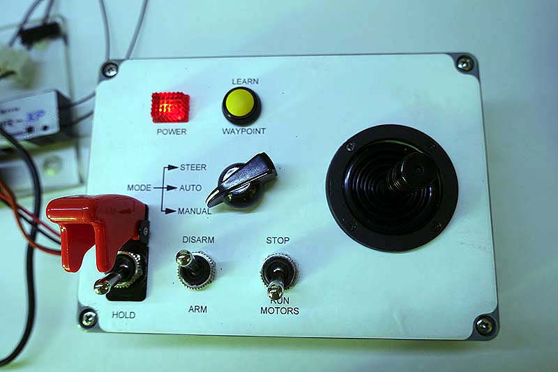
Our plan has been to build a local control panel on the rover to mimic an RC receiver. This would allow the rover to be driven around manually either walking beside it or sitting on it. If the initial trails are successful we will remove the remote RC radio and substitute this local control panel.
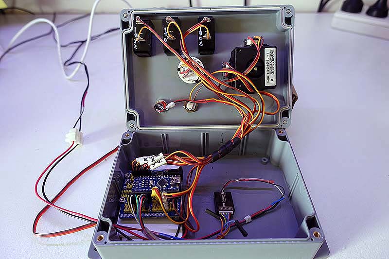
The one we have constructed has a joystick and a limited number of switches to provide the minimum functionality needed to drive the rover. An Arduino Uno is the brains doing the work.
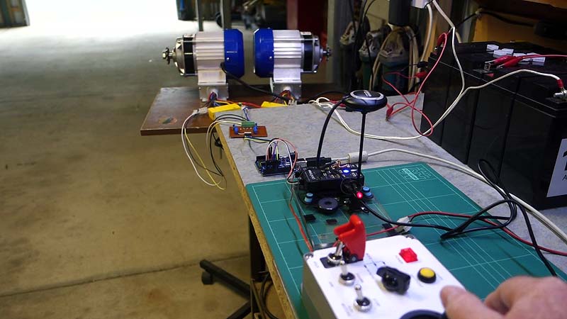
Our initial drive setup uses two ubiquitous 500W brushless motors and their controllers purchased off eBay. These controllers proved to be a nuisance in that the control signal required was an analogue voltage from 0.78v (stopped) to 3.05v (full speed) and with reverse achieved by switching a separate input wire. The other wrinkle was inbuilt maximum acceleration and deceleration rates. Visually these rates seemed a little slow but I was hopeful it wouldn’t give control problems others have experienced with slow actuators in their speed control systems.
To generate the required analogue voltage and reversing signal from the PWM control signal of the Pixhawk I used another Arduino Uno. Thus a PWM signal of 1000mSec generates a voltage of 3.05v and the reverse signal on, for 1500mSec the voltage was 0.78v and for 2000mSec the voltage is again 3.05v but the reverse signal is off. I included a small dead band at the centre to ensure the motors truly stopped.
The resultant drive system was installed with a test Pixhawk setup on our full sized feeder. Immediately obvious was that the top speed was too fast and so we reduced the control voltage range from 0.78-3.05v to the rather narrow 0.78-2.00v. With this range the top speed was about 1.5 metres/sec and despite the narrow voltage range the controllability was good.
Also immediately obvious was that the lack of strong engine braking from our brushless motor setup was a problem. Our hope that the brushless motors would remain in sync while slowing and provide the braking control was totally misplaced. If the speed was changed only gradually the motor controls functioned as designed and the rover drove well. However with sudden speed reductions the low rolling resistance combined with the relatively high weight of the rover meant that inertia quickly had the motors lose sync with their controllers. Control could only be re-established after the motors came to a complete stop.
Needless to say after a couple of heavy crashes into the retaining walls in my garden I came to the conclusion I had made a serious mistake.
We have decided to retreat to the more conventional brushed DC motors. These are now on order; TBC.
These VESC based motor controllers offer a lot of different configurations (engine braking), might be a learning curve to start with to configure them for your needs.
Not sure what amps you are pulling either.
I have used them on smaller projects they are very smooth.
Hi bill, thank you for all the updates and explanation it is helping me greatly for a garbage collecting rover i am working on.
i have some points can you tell if i understood your approach correctly:
You have 3 modes of controlling rover
a. Manual: By a hand held transmitter.
b. Steer: By sitting on the rover and control using the joysticks on the panel.
c. Auto: By marking waypoints for rover to autonomously follow.
My Questions are:
For manual control you are not using Pixhawk right ?? in that mode you just switch to Arduino nano which works by receiving signal from transmitter
Arduino job is to convert pwm signals to analog signal for motor controller ??
Steer Mode also works similar to manual right?
Auto mode: Does it require Arduino nano?? Pixhawk directly signals motor controller to reach the waypoints??
i am using sine wave 36V 350W EBIKE Sine Wave Brushless Motor Controller it has some brake wires and hall sensor wire are you using those in any way?
Hi ARNAV_MISHRA,
Welcome to the forum - you will find and absolute wealth of information here given by a lot of very kind and helpful enthusiasts.
You are correct with the 3 modes. At the moment we walk beside the rover and carry the control panel which is connected to the rover by a long curly cord.
In manual control the Arduino receives input from the joystick and sends the appropriate fake transmitter signals to the Pixhawk which is in manual mode and controls the motors. We do not have a RC transmitter or receiver connected to the rover, all control is via the local control panel.
No, the job of the Arduino is to take the positions of the switches and joystick and convert them into fake RC transmitter signals which are fed to the Pixhawk. The pixhawk controls the motors as normal.
Yes, steer mode is similar to manual. We found steer mode gave better control with the larger vehicle and skid steer.
Auto mode does not need the Arduino for the mission itself. The mission is loaded and monitored using a data radio from a remote computer linked to the Pixhawk (which is also used to supply GPS correction data from a local GPS base station). However I considered it very important to have an arm/disarm and emergency stop on the local panel for use during an auto mission.
The use of brushless drive motors were a problem for us. The ones I was using did not provide any engine braking and often lost sync with the controller which meant the rover had to come to a complete stop before restarting. My rover does not have any mechanical brakes and sometimes operates on sloping ground. We have converted to geared DC brushed motors controlled with a Sabertooth DC motor controller. This combination provides excellent motor braking; so much so that it is difficult to push the rover at all.
I will try to upload the circuit and Arduino code.
Bill