I use version 1.3.74 and Arducopter 4.0.3.
When I select the type of the second powermodul the following error message appears
After confirming in this field I can make a selection. Measure current and voltage.
When trying to select a sensor or enter a measured value, the following error messages will appear:
If I enter the value 14 for current and 13 for voltage in the parameter list, I do not get the correct values.
Despite many searches here in the forum I could not find a solution.
Can anyone here help me to solve this problem?
Make sure you’ve got the CUAV V5 firmware loaded, and probably do the boot loader update too.
You can also see in the “Messages” when you connect to MissionPlanner - it should say the board type
thanks for your answer.
I think that I did not express myself clearly.
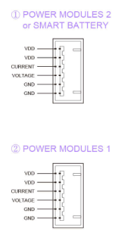
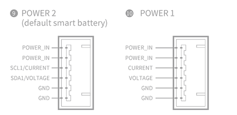
I have a HV PM module at power input 1 of the V5+.
However, I would like to use a second HV PM for redundancy reasons. Since the second current input of the V5+ only understands digital signals I want to use pins 13 and 14 as described in some of the articles.
However, the V5+ seems to have a problem here or there are other settings necessary that I don’t know yet.
The alternative is just hook up the second power module and dont worry about the voltage and current sensing (leave them disconnected) - test it on the ground but it should still provide power if PM1 fails. You just wont have the voltage and current readings. You’d probably want to RTL or LAND when something that drastic goes wrong anyway.
The diagram is a bit strange actually, it indicates there’s the possibility of using a standard power brick for Power2 but there’s no mention of how to change it.
Over at PX4 they actually say: Do not plug Digital or Analog PM onto connectors configured for other type of PM
If you plug an Analog PM into a digital PM connector it will stop all the I2C devices on that bus. Specifically this will stop the GPS’s compass due to contention, and may also damage the FMU (longer term). Similarly, a digital PM plugged into a analog connector will not work, and may also damage/destroy the power module (longer term).
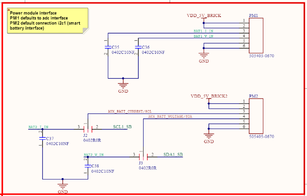
OK found it - there’s two jumpers somewhere in the base, J2 and J3: