Hi,
I read that pwm input from flow sensors are supported reusing the BATTMonitor which is amazing. However, i have 2 sensors that provide PWM output. So my question is, if i configure 2 AUX ports as GPIO, is it possible to read out both incoming PWM values somehow via mavlink?
Hi @Robert_Driller,
So I guess you mean fuel flow sensors.
The wiki page is quite hard to understand but it seems you’ll need to do this:
- set SERVOx_FUNCTION to -1 to reconfigure two PWM outputs to be GPIO inputs (e.g. SERVO9_FUNCTION = -1, SERVO10_FUNCTION=-1)
- set BATTx_MONITOR to 11 to setup two battery monitors to be fuel flow monitors (e.g. BATT_MONITOR=11, BATT2_MONITOR=11)
- set BATTx_CURR_PIN to the magic value for the PWM outout (now a GPIO input). Hopefully you’re using a Pixhawk or Cube which I think has all the values displayed in the parameter descriptions. If not then it’s a bit more difficult to find out what the number should be (this is what the scary picture showing the hwdef.dat file is trying to get across)
- set BATTx_AMP_PERVLT to convert the sensor’s PWM output into milliliters consumed
Oh really, it is possible to configure 2 battery monitors. Amazing, i will test that and report my results here to close the thread
1 Like
Hi it took me a while, due to lack of time and the reason that I still could not fix it.
I am fully aware that the problem i am having is not ardupilot related but still maybe someone has more experience an can give me a hint.
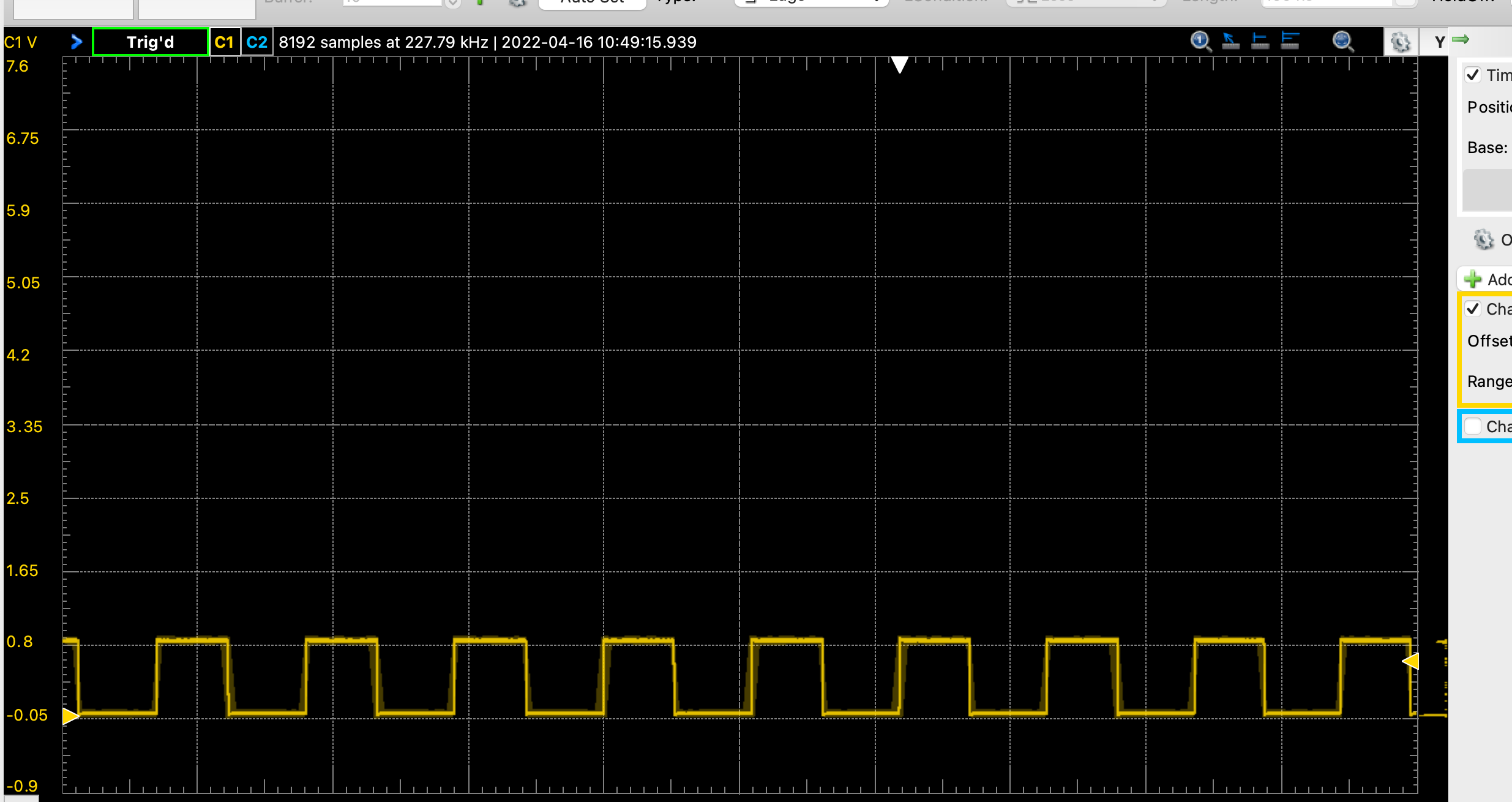
My sensor provides a nice PWM in a “dry” setup with a 1,5k pullup 5v power supply.
However, when plugging into the Pixhawk V3.0 the pullup seems to fight an internal pulldown. The voltage drops to about 0.9V. It still provides a good pwm but with the wrong levels.
After some searching in the docu I tried 2 things so far: Base on Buttons — Rover documentation I tried removing the pullup completely since it states that
These pins will have an internal pullup assigned to them automatically,
that did not work. It was a bit like a very noisy PWM on 5V level.
based on Fuel Flow and Level Sensors — Rover documentation I tried a pullup to 3.3V with a 10K even though that does not comply with the specs of my flow sensor.
Any GPIO capable pin on the autopilot can be used to connect to the sensor’s output. If it is an open-collector output, a 10Kohm external resistor pull-up to 3.3V will be required
This also did not give me the desired result just a very low level PWM at around 0,3V
I have no idea about the inner schematics of the Pixhawk, maybe someone in this forum has a good idea, thanks!!
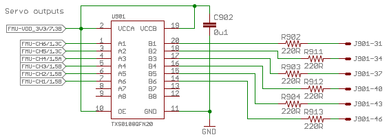
From the classical Pixhawk schematics, this is AUX’s hardware: TXS0108QFN20 supplied at 3.3V, with resistors. You can check visually if yours is like this.
I am afraid not. I bought a Radiolink and it seems that they do not have this Level Shifter. I will also direct the question to them to understand the logic behind.


It seems so. So you can insert some glue TTL logic (pairs of HCT14 inverters, HCT244, HCT245…) supplied from Pixhawk or try a different Pixhawk, and check levels on oscilloscope.
I use GPIO AUX 50, 51,52,53,54 on Rover Ver.4.1 on CubeBlack, it works for some switch device control, when I use Rover Ver4.2, and set SERVO1_FUNCTION = -1, SERVO2_FUNCTION = -1, SERVO3_FUNCTION = -1, SERVO4_FUNCTION = -1, SERVO5_FUNCTION = -1
it does not work.
How to use GPIO output and input in Ver4.2
I have figured out. Servo9-Servo14 is for AUX 50-55