Hey everyone! I’m new to this, and I’m leading a senior design team at my university using autonomous helicopters.
We had a crash that was pretty interesting last week: our Goblin RAW 420 was flying fine in stabilize mode, then we got a compass variance error, EKF error, and yaw imbalance 32% error.
We put it in return to home and all of a sudden it started spinning very fast about the yaw axis. In the gdrive is the bin file, a video of the crash, and the current settings on Mission Planner for the Helo (too big to attach here).
I’m stuck trying to figure out what’s wrong, and don’t have the money to be able to fly again until we have the answer to what in the software is making it spin so weirdly. My best guess is that there is possible magnetic interference from the direct drive motor causing compass variance issues? But that shouldn’t make it spin like this, right?
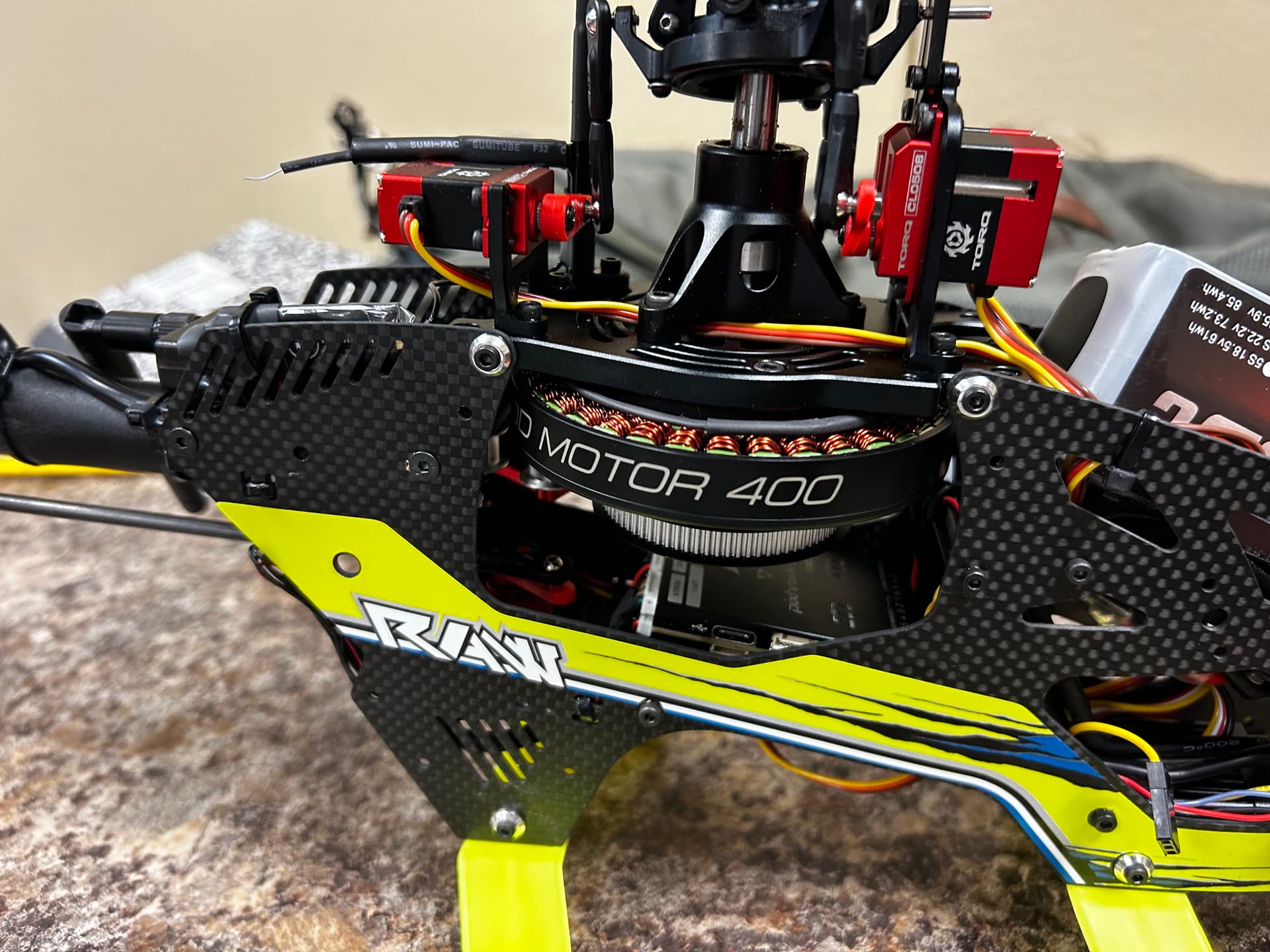
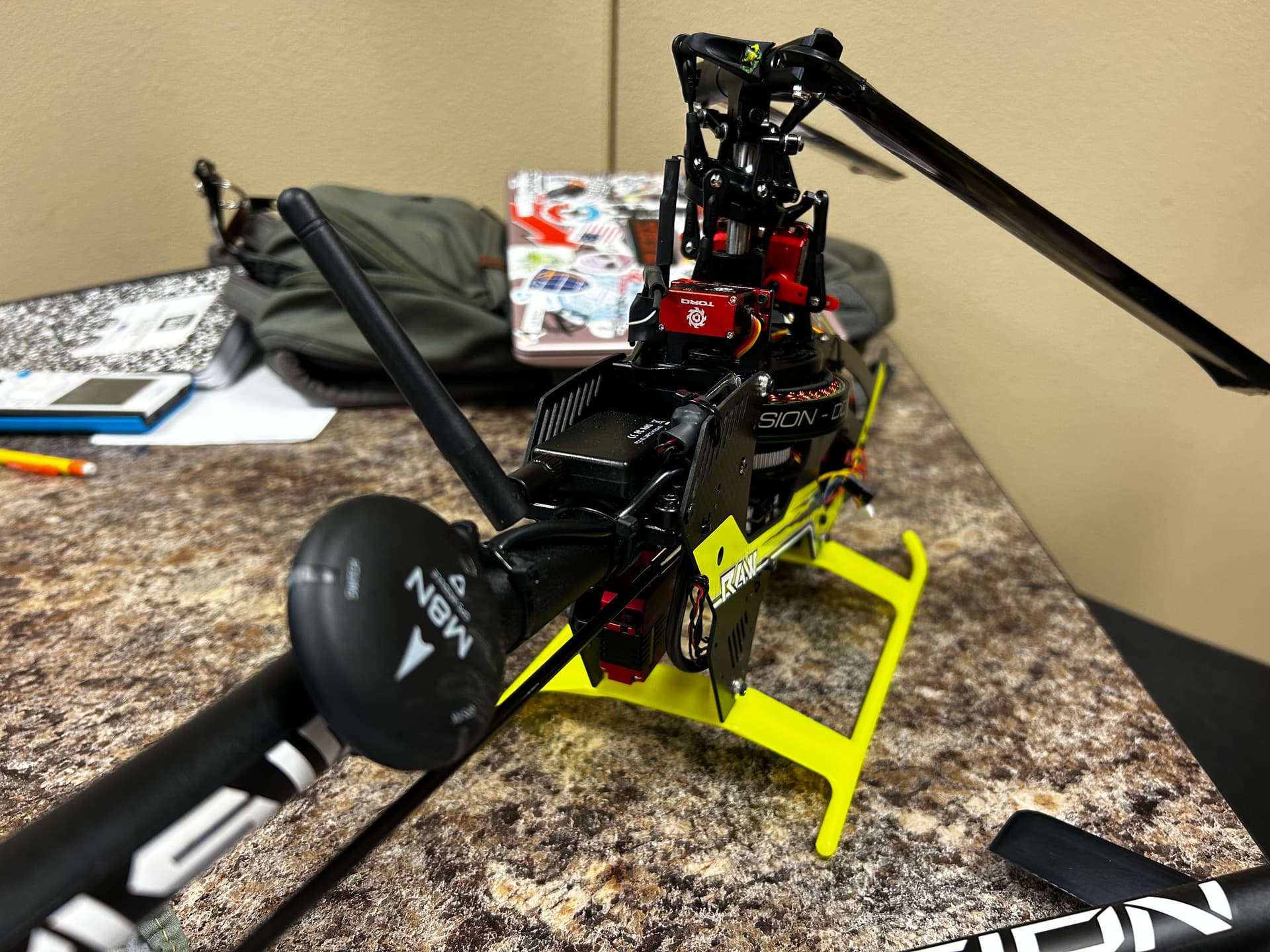
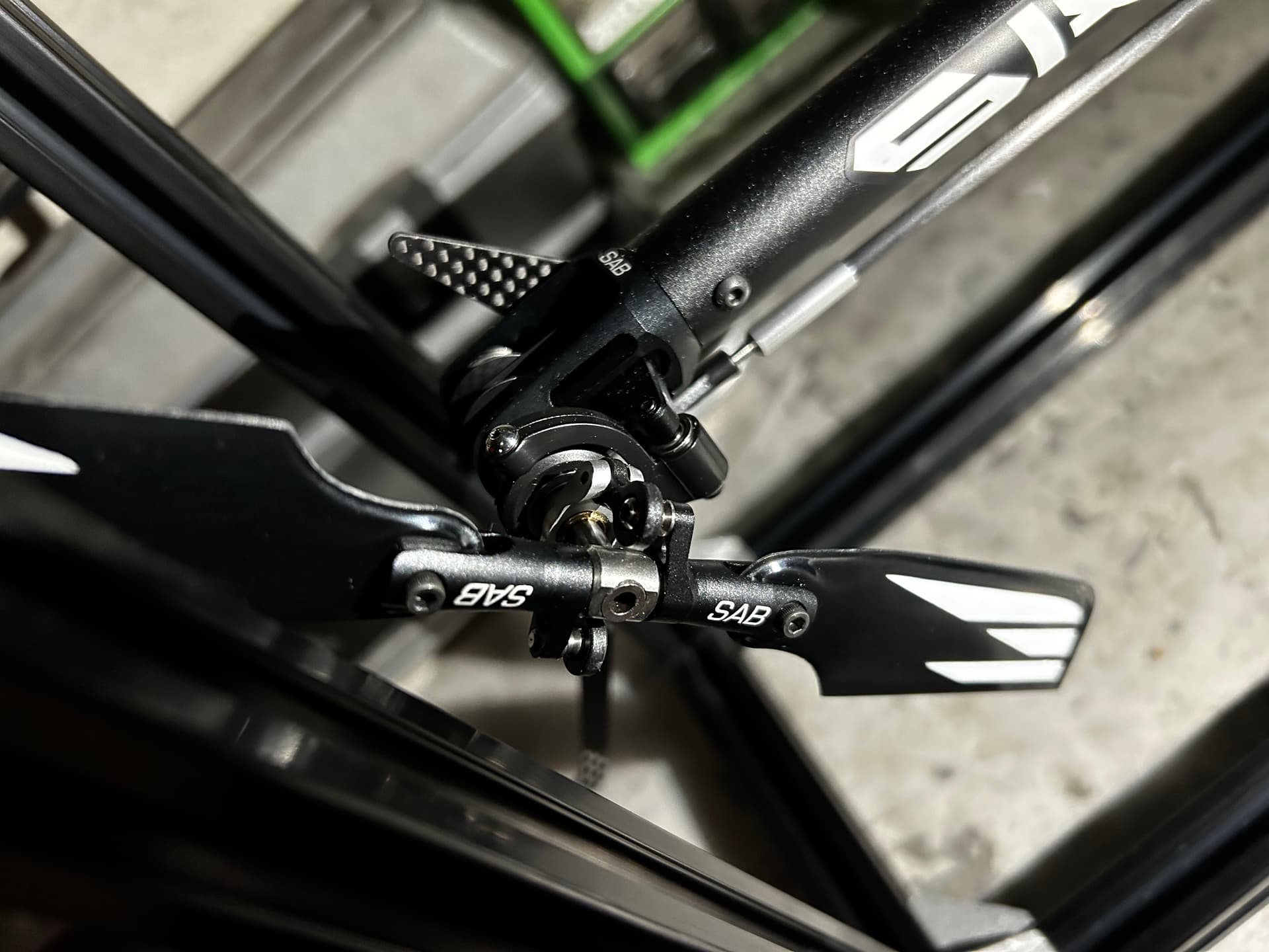
By the way, we are using a Pixhawk 6C Mini FC Module Flight Controller STM32H743 Processor with PM02-12S Power Module and M8N GPS. The GPS/Compass is tail-boom mounted and is about 6 inches from the motor. The Pixhawk is installed in the belly of the fuselage directly under the motor.
These photos are taken after the crash, but it’ll show where the fc and gps are mounted if that helps diagnose this at all.
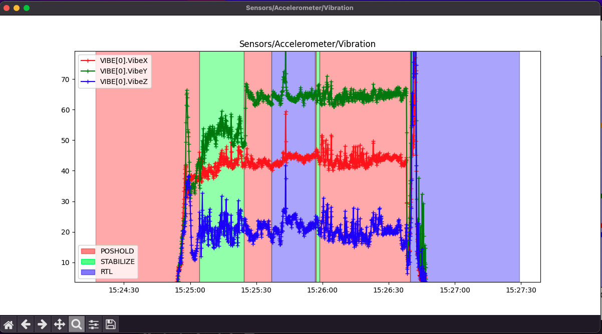
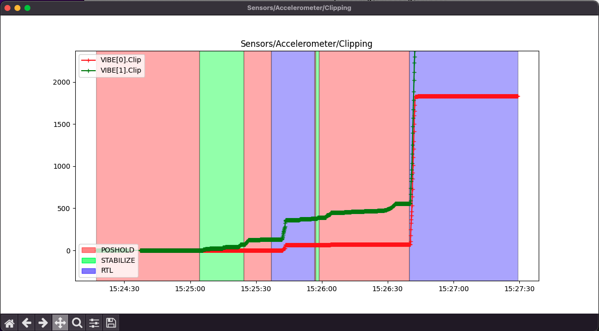
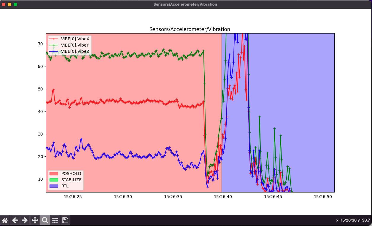
Vibrations are a big issue. Enough that the IMUs are clipping. I would say it’s a balance problem given the axis (X&Y), but it could also be related to how the FC is mounted to the airframe. This can cause the EKF errors. This is a mechanical issue and would need to be addressed before getting too far into any firmware problems.
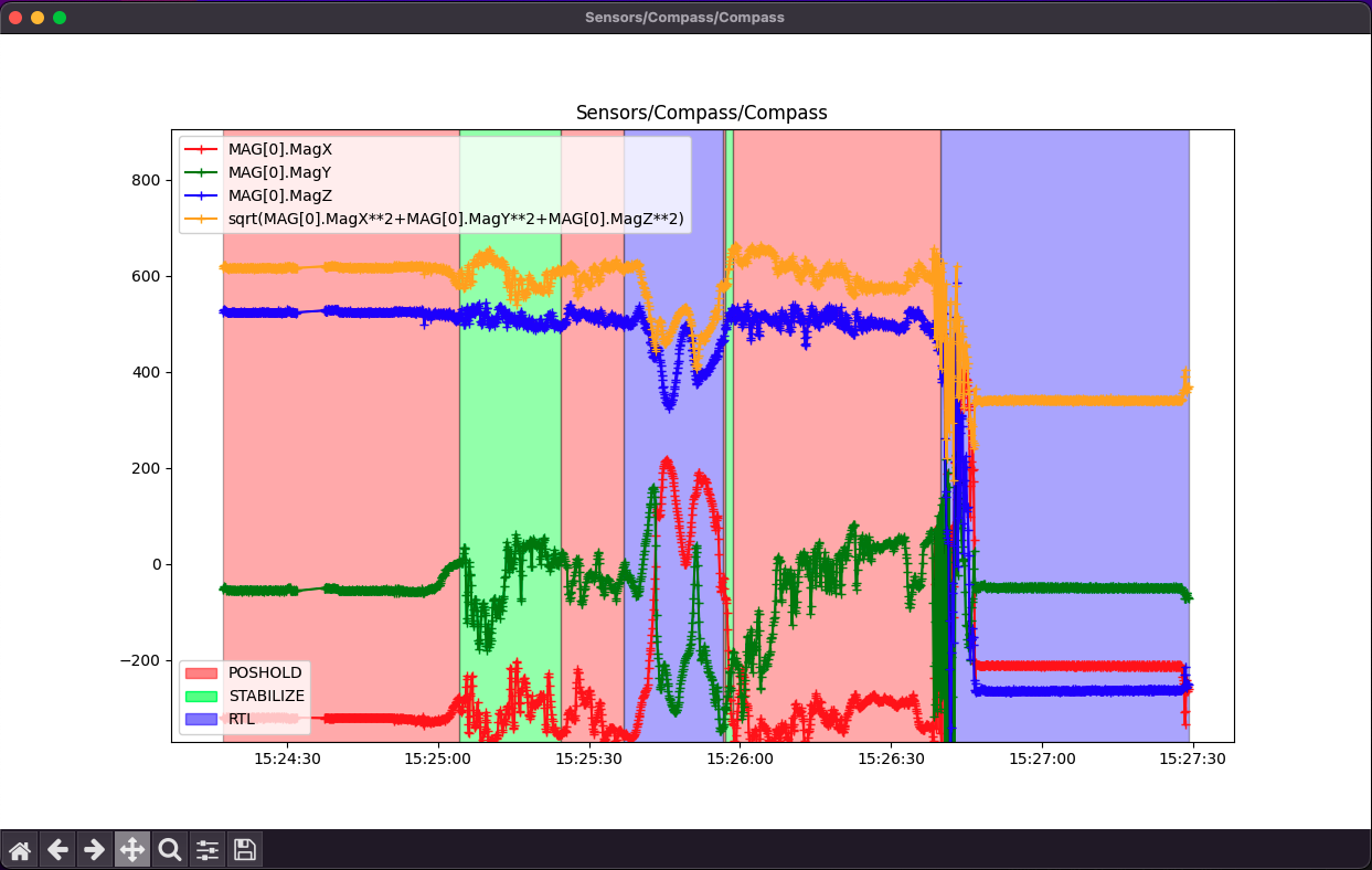
The compass is suffering from interference. This could be cleaned up with a MagFit calibration once you’re flying again. This interference can cause the variance errors. The heli has current monitoring so this calibration will take current levels into account for the compass values.
There’s something else bugging me here. I realized that just before it went into RTL there’s a significant drop in vibrations, and noticeable drop in current. (from 10 to about 5 amps)
Thank you so much for your response! This is incredibly helpful.
As for the FC placement, where else on a Helo this small would be a good place for it? Is the issue that it is directly under the motor?
What else should I look into to fix the mechanical vibrations? Would this be something that’s done with a notch filter in setup, or is it more of a mechanical balance thing than that?
Is it possible that the compass is too close to the motor, or is that distance alright?
As for the vibration letting go right before the spin, are you saying that it was probably a mechanical failure that caused it rather than a software issue? We made sure everything was tensioned well before the flight and that there were no obvious issues with that system in preflight. Do you have any idea what may have caused it (i.e. belt slipping etc.)? The tail rotor is belt driven from the main drive motor. Could this be a calibration issue, or does a spin like that need to be more of a mechanical issue? Also, does it make sense that the current would drop 5A if the tail rotor is driven by the same motor as the main rotor?
Also, what software are you using to graph those datapoints, it looks really nice!
Sorry for all of the questions, I’m really new to this and don’t want to assume anything incorrectly!
It may not be as much the issue of where, but how. You might need to look into a soft mount or damping for the FC. Directly under the motor might be an issue, but on this airframe there might not be a ton of choice. Hopefully somebody who knows the platform specifically can provide some suggestions.
You will need to look at the rotor head, the main blades, drive shaft, belt, tail rotor, etc. anything that’s moving. Have you statically balanced the blades? The notch filter will help address some noise to the IMU but mechanical vibrations can’t be cleaned up in software. Coming from a manned helicopter background, I’ll say that vibrations will lead to premature failure of components. The sudden drop in vibrations and current suggest to me that something stopped moving, but didn’t bind up. It could be a failure of the motor wiring (one phase let go), or maybe a belt failed and removed the electrical load on the motor.
It may help to try and figure out what direction the helicopter was spinning. Was it torque or anti-torque? I’m going to guess (and this is really a guess) that it was spinning with torque and that would suggest a failure to the tail rotor system.
I use MavExplorer to look at log files. It’s part of Mavproxy. It’s very powerful but not as user friendly as the Mission Planner log tools. But because I jump between Windows, Mac, and Linux, it about the one program I use that is consistent between all the platforms.
I’ll look into how we have the FC mounted currently and see if that’s an issue and hopefully someone can give some suggestions.
We had a couple hard landings over the course of the helo’s setup that may have jostled some of our components. I don’t think we rebalanced or did another calibration after those besides the normal preflight ardupilot does.
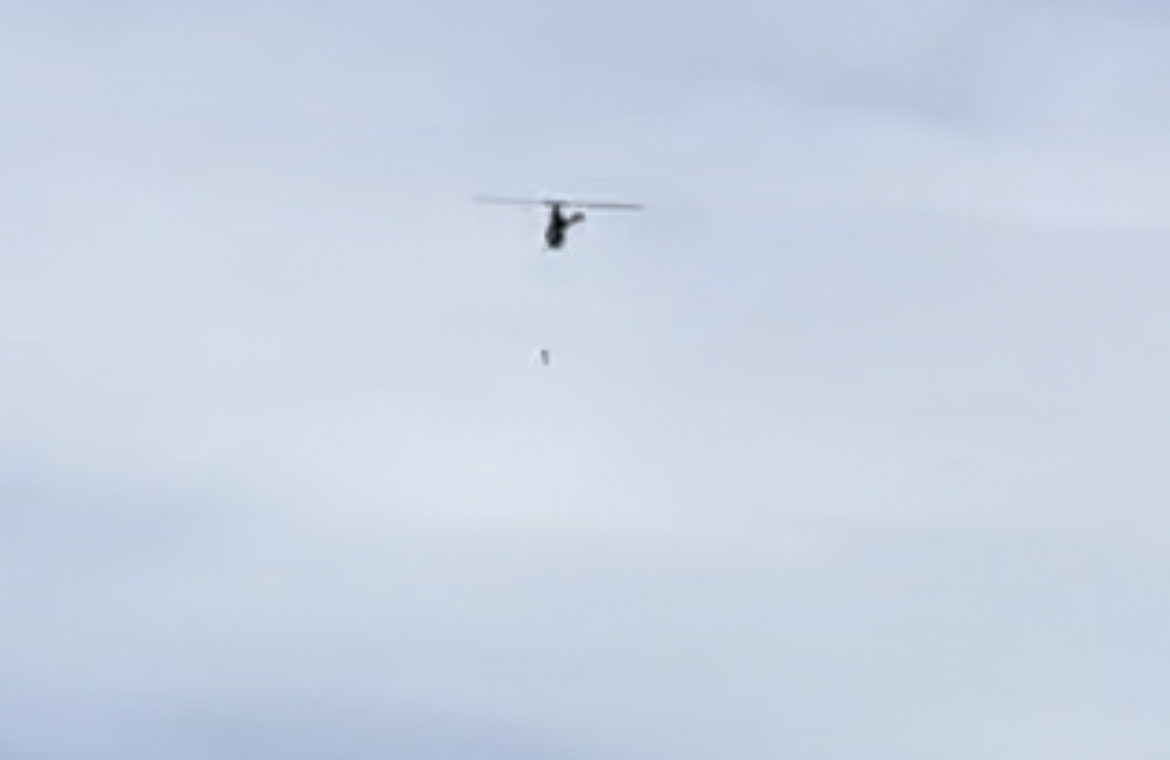
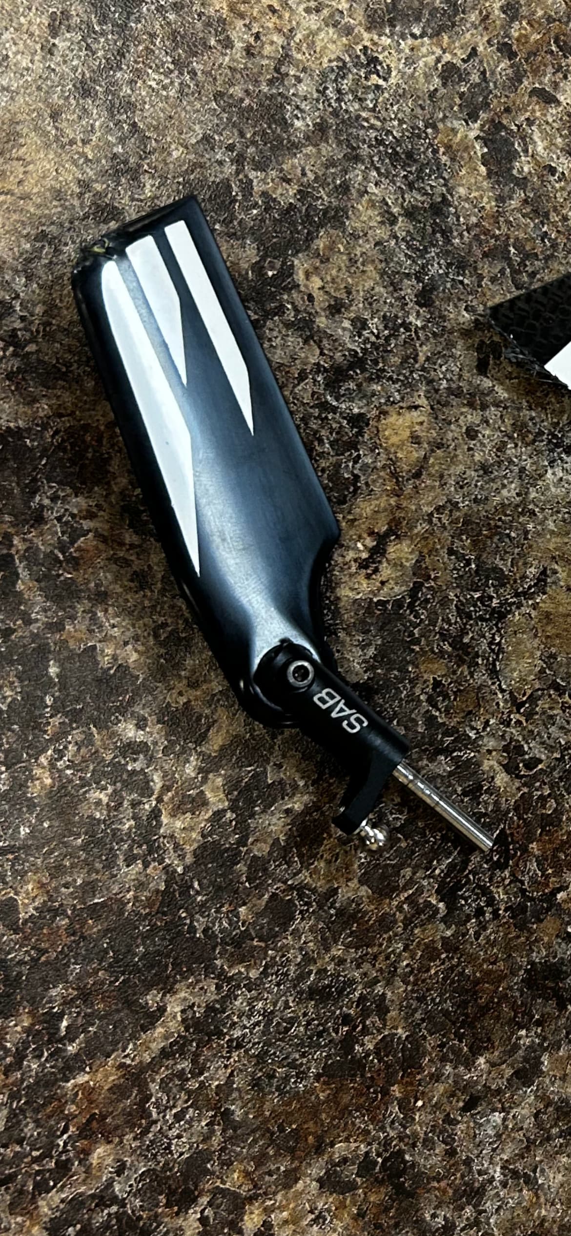
I looked into this a bit more and you are totally right. In the video the helicopter started spinning with torque. I looked a bit closer and you can see something fly off of the tail rotor assembly just before it started spinning:
First, I am sorry to hear of your crash. Are you based in the U.S.?
Did you inspect the aircraft to determine what came off? If you can see it in the video then it has to be something you could determine through inspection.
One thing to point out about helicopters, be sure that you use thread lock on all your bolts that aren’t being screwed into a self locking nut. If you built it from a kit, I’m sure they showed where to apply thread lock. With a new heli, it is good to check them after the first few flights to ensure nothing is coming loose.
Yes, because since the body is now spinning with the rotor system, there is significantly less torque to keep the rotor spinning.
Thank you for your reply! Yes, we are at a University in Texas!
We did inspect post-crash; unfortunately, a lot of parts were strewn about our field after impact. I believe we tracked everything down except one of the tail rotor blades (I believe it is what came off) and now that we see it in video, I want to go look for it.
We did use thread locker, and even after the crash all of the bolts on the rotor assembly look intact, but the tail rotor itself was beaten pretty badly as it struck the ground first.
We were having so many software issues and are so new to ardupilot that I guess we didn’t think it was mechanical! But, we are going to do a much more thorough inspection now that we know it was an issue related to the physical assembly. I mentioned we had a few hard landings and autorotation’s due to the motor shutting off on us due to a failsafe we hadn’t set up correctly, and I’m thinking we must have damaged the tail rotor assembly and just didn’t notice it upon preflight.
Is there anything else we should look for or any other checks we should implement to make sure that this doesn’t happen again? I’m going to look at getting live graphing using MavProxy to hopefully diagnose any vibrations before it turns into this… Do you know if mission planner has a live plot feature that would allow us to do this easily?
There are a few options for live data in Mission planner. On the HUD you should see the word Vibe. If you click on that you’ll get a display of the current vibration levels in a popup window. EKF will do the same kind of pop up. On the bottom of the map tile there is a check box beside Tuning. If you select that the map will cut in half and you’ll get a dynamic graph. You can double click on the graph and a window will appear with all the possible data points you can graph. Tip: don’t try to graph too much here at one time. It just gets ugly.
The status tab also has the live vibe numbers, but that’s pretty hard to read during flight.
Just keep in mind they only update at your telemetry rate, so they won’t be as detailed as the graphs from the .bin logs.
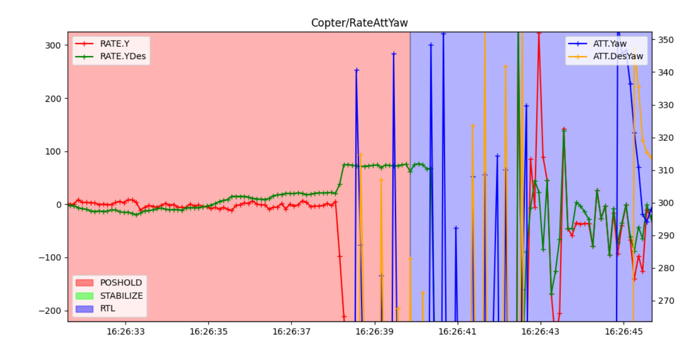
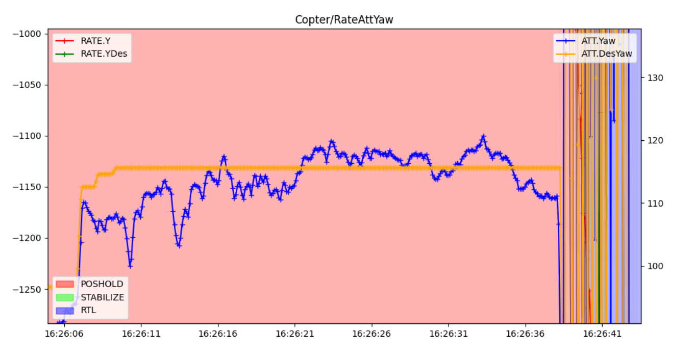
Looking at the desired yaw vs the actual yaw for the flight, from an untrained eye, it looks like the software does “desire” to spin (in yellow on the right just before RTL). Am I reading this correctly, or is it just trying to compensate for the loss of the tail rotor? is there something else that I should be looking into for a software change once we get it rebuilt to try and make sure things go more smoothly?
Thank you! I think that’s exactly what we’re looking for. Hopefully we can monitor the vibrations in the future.
As for the tail rotor coming off, I think the blade gripper assembly failed during the hard landing we had prior and we just missed it. My best current guess is that one of the grippers must have dislodged and come off during the flight causing the spin.
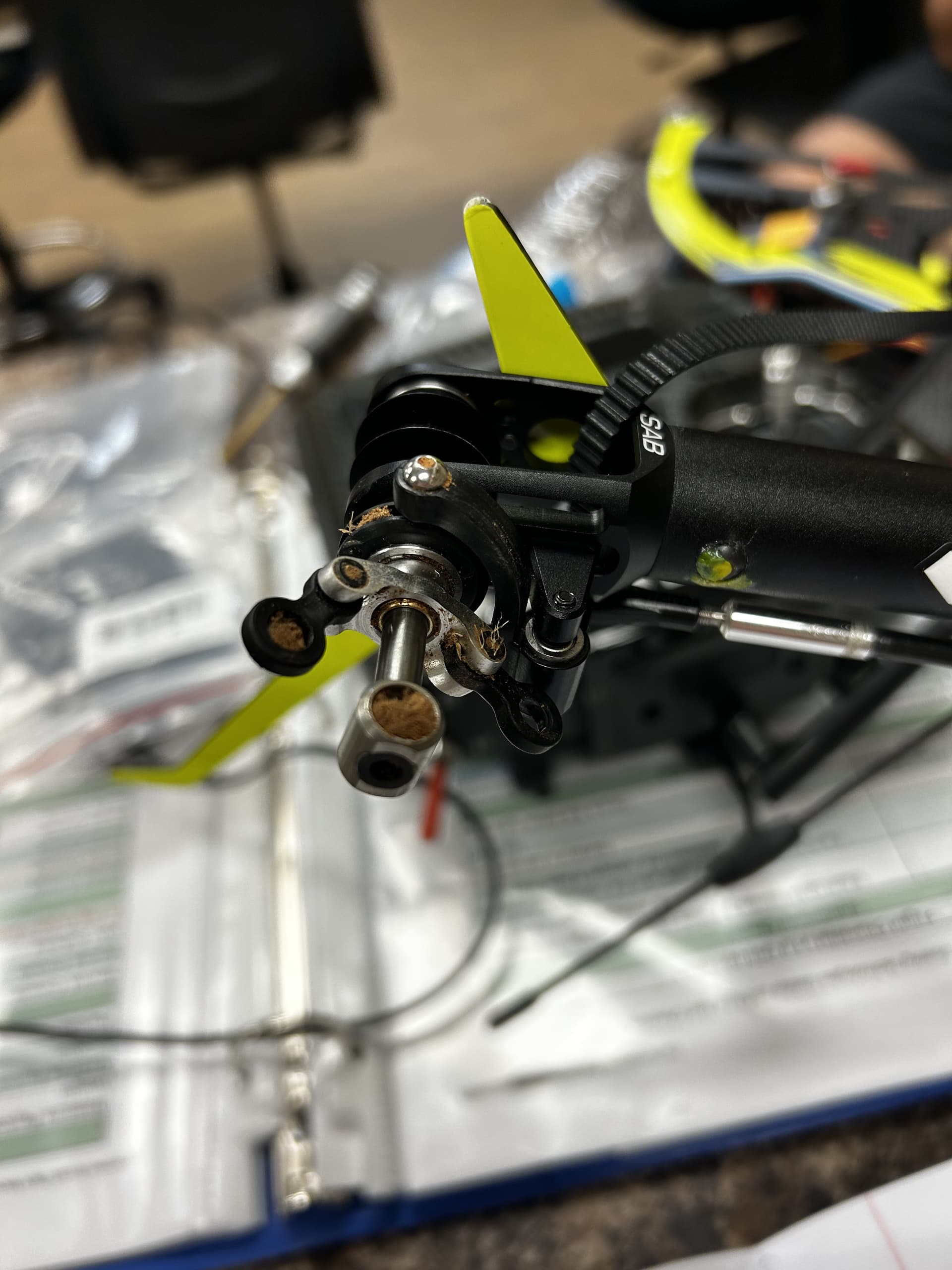
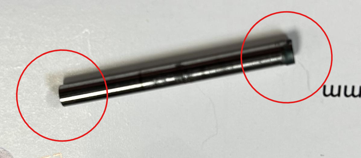
We just did an inspection of the crashed tail rotor assembly, and after taking what we could find apart, the center shaft that contains the thrust bearings and holds the gripper arms for the tail blades looks like it was our failed part. There are two screws on either side that hold it on the tail slider shaft. One screw is missing (somewhere in the field), and the other was still intact within the blade grip (shown above). After taking this part off and inspecting the center shaft that holds the blades, one side looks like it was thread locked, and the other has no signs of thread locking at all. I believe when our team was assembling this, we must have forgot to thread lock that side and it worked itself out over time.
@LinkRaymond just a little flight safety advice…avoid to fly “overhead”, judging attitude and vertical speed of the aircraft becomes more difficult and your safety buffer is significantly decreased.
@Peter_Glukhovsky Why do you say that? If the ESC has a governor then you would use mode 2. I encourage users to stay away from mode 1 (RSC passthrough). It could cause a crash if it is not set up correctly.
Governor mode goes w/ flat TC but I see H_RSC_THRCRV_0,25
H_RSC_THRCRV_100,100
H_RSC_THRCRV_25,32
H_RSC_THRCRV_50,38
H_RSC_THRCRV_75,50 (good for Mode 3)
@Peter_Glukhovsky
yes, mode 2 is one value because the ESC is maintaining the motor speed at a constant value with ESCs internal governor.
Mode 4 is the ardupilot governor that uses the throttle curve set through the parameters that you posted. The throttle curve can also be used by itself with no governor.
I would recommend the ESCs internal governor unless it doesn’t have one. Then use the ardupilot governor, mode 4