I just tested my Arducopter’s internal governor for the 1st time yesterday. It seemed to work to some degrees, but I have many problems. My throttle curve is 25-37-42-61-100 for the O.S. GT15HZII engine. The zero pitch position (measured using pitch gauge) in the collective is when the collective stick at about 25%. (I target -2 to 12 degrees for UAV). When I enable the motor interlock, the governor does not engaged, I have to raise the collective stick and really take off from the ground, then at some height, I can feel the engine start to spool up. I guess that’s what the internal RSC governor document said about “at least 50% RPM” at flat pitch. But my 50% RPM is at the pitch of at least 4 degrees. Does that mean for autonomous mode to use governor, I have to modify my throttle curve so that at 0 pitch, it will have at least 50% RPM for the governor to engage on the ground?
Another problem I have is that I set the governor’s H_RSC_GOV_RPM = 1700, H_RSC_GOV_RANGE=100, but the dataflash log shows it only has about that 1500 rpm. I used Hall sensor at the engine fan, but set the RPM1_SCALING = 1/(gear ratio). The RPM seemed to hold as near constant, but not the 1700 as I specified.
Hi @steveross1234 , I’ll answer here. I suggest to first tune your throttle curve (so set H_RSC_MODE to 3) to get a bit closer to your desired setpoint of 1700 rpm, it’s still too far away.
I would suggest to increase H_RSC_THRCRV_0 to 30, H_RSC_THRCRV_25 to 40, H_RSC_THRCRV_50 to 50.
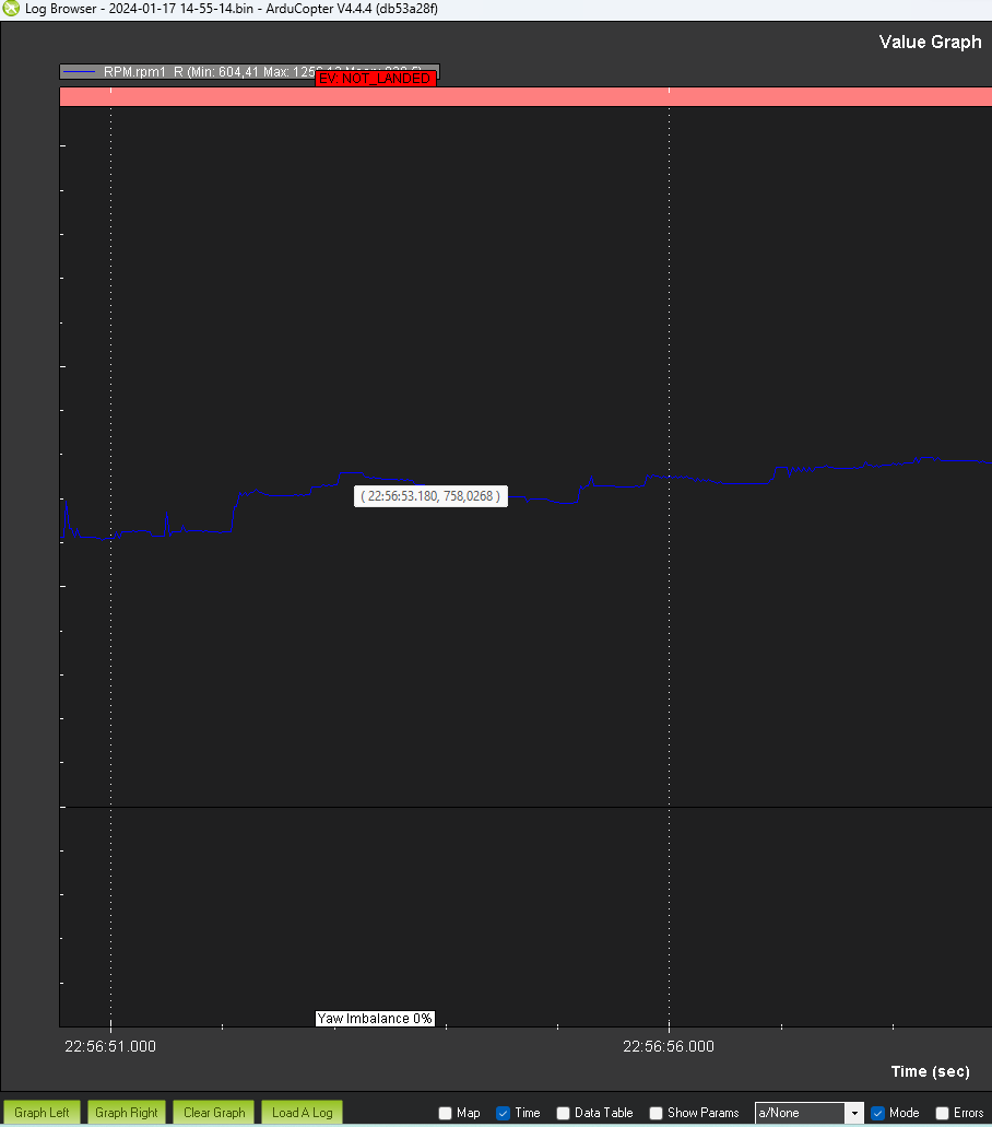
You did a takeoff with 760 rpm!
Ideally, you want the heli “light on the skids” with a headspeed not less than 90% of your desired headspeed while tuning the throttle curve.
Once you’re done with tuning the throttle curve, you can set H_RSC_MODE back to 4 but change the following for a start:
H_RSC_GOV_DROOP → 10
H_RSC_GOV_FF → 15
The EKF problems seems to be related to the GPS/compass module:
Thanks for the answers. The GPS is mounted in the tail boom with a 3D printed mount (with zip ties to hold on tail boom). The GPS is glued to the mount with 3M thin (1mm) but strong black colored mounting tape.
Should I add damping rubber mount for GPS/Compass?
The tail is belt drive. My flight controller is at front, above the engine fan. I have to build a very long cable for GPS module to connect to the flight controller. I am afraid this long cable causes EKF errors.
I built a new long GPS cable using the Teflon insulated wires (previously I used PVC insulated wires), now the EKF errors are gone.
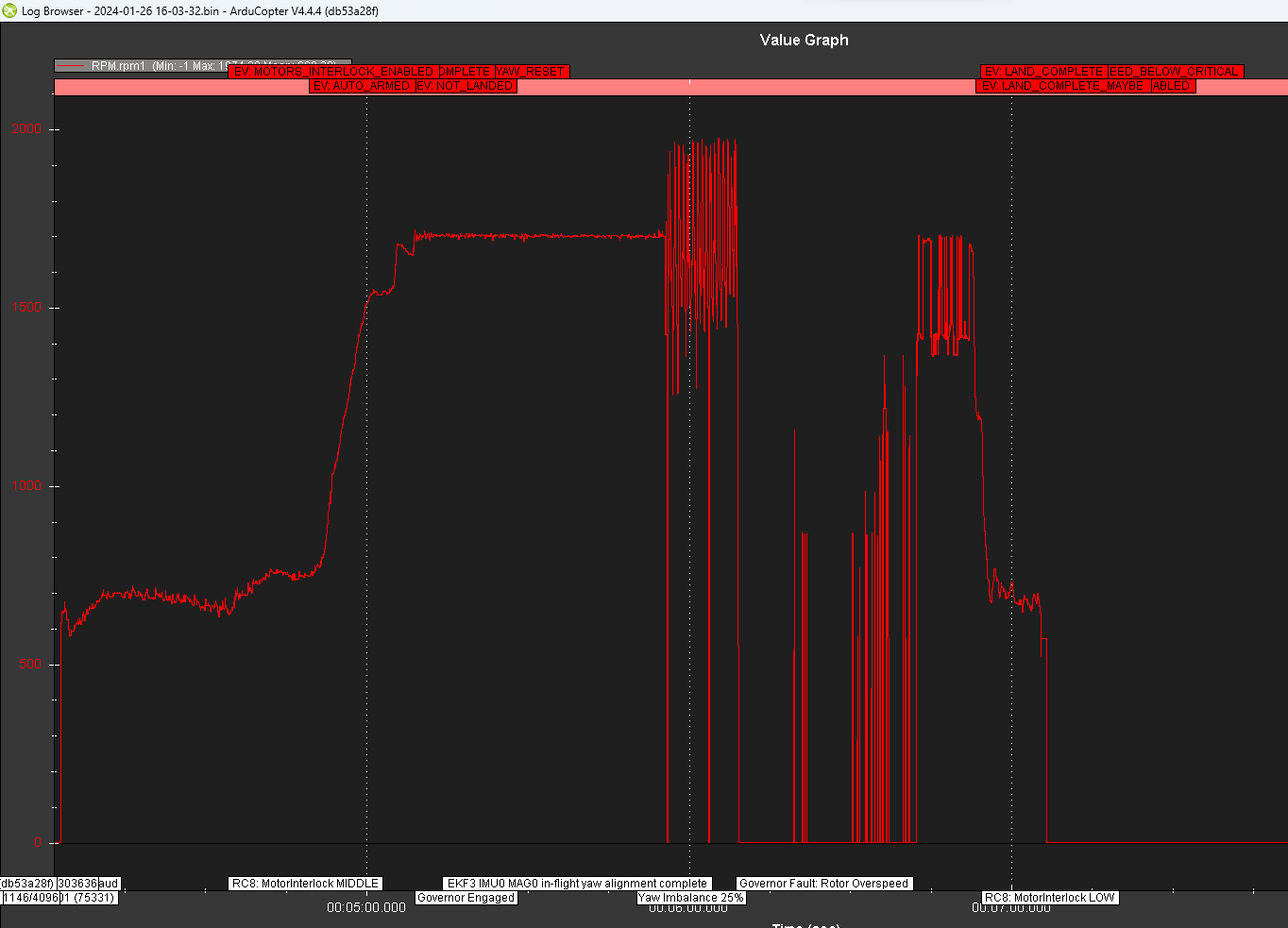
I did many test flights on the throttle curves and experiments on the different H_RSC_GOV parameters, I can see the internal RSC governor has engaged and worked for a while but later got Rotor Over Speed fault or Rotor Under Speed fault. My RPM sensor is on the engine fan, and set rpm1_scaling to 1/(gear ratio) and used rpm library to report the rotor rpm, and I hope that the internal RSC governor will work. Have you ever succeeded in tuning the internal RSC governor using the RPM sensor on the engine speed with the RPM1_Scaling?
Chris’s document on internal RSC governor mentioned something about “surge” or “over-react” or “Hunting”. I am not sure what they mean. I did notice that in several occasions, my engine rpm suddenly went up and down several times for a while, after governor has engaged and engine ran smoothly before that.
Which parameter should I change for Rotor Over speed fault? Which parameter should I change for Rotor Under Speed fault?
Hi @steveross1234 ,
looking at the logs you linked it seems to me that you have some troubles in the rpm reading rather than governor settings. Or at least, you should first sort the rpm sensor and then focus on the tuning of the governor.
Look here:
The “drops” to zero rpm are not real and most likely caused by a miscontact or electrical issue on the sensor.
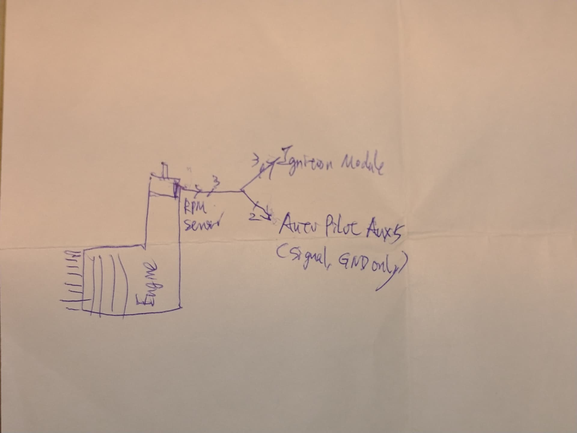
Did you use an Hall sensor with magnet mounted on the cooling fan? Since you use the GT15HZ you could easily add a Y to the engine rpm ignition cable (the one that goes on the crankshaft used for timing of the spark plug) and retrieve rpm from there instead of adding an external sensor.
I think Throttle Curve looks much better now.
yes, although I don’t use scaling, I prefer to be consistent with what I’m measuring (not a real problem doing otherwise).
None, at the moment.
These logics are there to protect the system against sensor problems or really badly tuned governor/throttle curve. From the rpm plot I can see rpm holding fairly well before the sensor problem popped up (causing the governor to quit and revert back to throttle curve), so the initial tuning is not an issue in this case.
Thanks a lot for the help. I just built a new RPM sensor (Align Beastx) with pull-up resister added in its cable, will do test flights soon to see if that works.
The magnets for my RPM sensor is mount on the engine cooling fan.
Have you succeed in using Y-cable to feed the RPM signal from O.S. GT15HZ to Autopilot? Do you need to add pull-up resistor for this RPM signal to be used in HV servo rail in autopilot? I worried about the cross talk from the ignition module will go from this Y-cable to interfere the autopilot. Previously, I use a single LiPo battery for servos, autopilot, and ignition module. I got very severe interefernce (noise) in the shared DC power rail. I later added a IBEC (ignition BEC) that decouple the ignition module’s power from the rest of the system, and the voltage in power rail for autopilot looks much better after that.
I did several test flights using the Align BeastX RPM sensor with pull-up resistors. The result are disastrous. The RPM have large up and down variations and got governor over speed fault from the beginning.
My previous RPM sensor (sometimes RPM goes to zero) is from Aerospire. Initially, I cannot get a reading in my Pixhawk, after I added a pull-up resistor, I can get a reading from Pixhawk (RPM sensor connected to HV servo rail Aux port).
I thought Aerospire’s RPM sensor uses Melexis US5881 Hall Sensor chip, so I bought a few these chips, and build a new RPM sensor, however, I cannot get a reading from Pixhawk (connected to HV servo rail), whit or without pull-up resistor. In Arduino, it works without pull-up resistor. Do you know which chip is used by Aerospire?
There is no crosstalk, the sensor is outputting the square wave, autopilot and ignition unit are just listening. On the line going fom the Y to the autopilot just connect signal and ground wires (not +).
yeah, better separate sources.
I have done in this way using Zenoah PUH engines equipped with RCexl ignition units (very similar to the OS one) and it works flawless, without any resistor (I do not like soldering/adding this kind of stuff to gassers-vibrations and soldering do not cope well). I would give a try with the OS ignition unit too, but I don’t currently have that engine. If you have access to a logic analyzer you might want to check voltage levels and cleanliness of the square wave from the sensor.
I made a Y-cable (neither pull-up resistor nor V+ from Y-cable to Autopilot) to feed the O.S. GT15HZII engine’s RPM to the Aux5 (Pin 54), and did several test flights. I got Internal Error, ISR Flood on Pin 54.
Do you know how to overcome this ISR Flooding on RPM signal? Will adding a Pull-up resistor help? If I use an external governor instead of the internal RSC governor, will this ISR flooding be resolved?
Hi Steve, I looked at your logs and I see the same behavior on rpm measure as when previous sensor was used.
You could try adding a resistor, did you check by any chance with the logic analyzer? What flight control is this?
Thanks for the picture.
Which voltage V+ is comming from the ignitor module which max voltage has the signal line?
What are your settings for the aux port 5 pin 54.
And as also Ferrosan asked, which FP (Brand & Model) you are using?
The V+ are coming from the O.S. ignition module, which is provided by an IBEC (ignition BEC) with 8 volt. I don’t know the max voltage of the RPM signal line. This V+ does not go to the autopilot. The autopilot I used is Pixhawk 2.4.8. The Aux5 is set as GPIO, rpm1.
How should I add the resistor? in-line or pull-up? Should I add the resistor before the Y-cable (between the engine’ RPM sensor and the Y-cable? Since I don’t have V+ between Y-cable and the autopilot, I guess the resistor should be added just after the engine’s RPM sensor and before the Y-cable. Is it correct? My autopilot is Pixhawk 2.4.8.
Do you have more information about your PixHawk 2.4.8. I think this one of the low cost chinese copies and probably not 100% identical to the pixhawk schematics linked here.
If the voltage of the IBEC is 8V than probably also the signal of the RPM sensor goes up to near 8V and this might be to much for the input pin of the pixhawk depending on the circuit behind.
Which possibilities you have to measure the signal line?