Hi I’m trying to set up a harmonic notch based on the throttle, to determine the reference frequency I use the tool ArduPilot Web Tools
How to understand that the autopilot uses the INS_HNTCH settings. I set the settings as indicated in Measuring Vibration with IMU Batch Sampler — Copter documentation
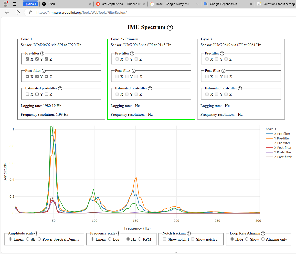
to record data before and after filtering. I understand correctly that on the graphs I can only see the result of INS_GYRO_FILTER=20 and INS_ACCEL _FILTER=10?
How close can the frequency be in INS_HNTCH_FREQ with INS_GYRO_FILTER=20?
How to understand that low-pass notch filters do not have a large phase delay and do not affect stability?
Tomorrow I will attach log files with test flights.
If you use the Initial Parameters section in MissionPlanner then the INS_GYRO_FILTER value would be less than you motor noise frequency (and this is normal) so then INS_HNTCH_FREQ will be determined by the FFT graphs from a test flight.
Set these as a starting point:
I can even estimate what frequency and bandwidth you will need based on your prop size, but a .bin log will be better.
Here is the “general” settings and rules you would use for throttle-based notch filter:
INS_HNTCH_MODE,1
INS_HNTCH_BW, peak_freq / 2
INS_HNTCH_FREQ, peak freq from FFT
INS_HNTCH_FM_RAT,0.7
INS_HNTCH_HMNCS,3
INS_HNTCH_REF, hover_thrust x 0.6
The REF value has an actual formula to calculate it correctly, but in reality 60% or 70% of the hover thrust value is near enough and can easily be refined via the web tool.
Use the least number of harmonics and other options required to just do the job.
Get a log file and we can step through the process.
You have a cube orange, and the primary IMU is #2, so you’ll need to set IMU_LOG_BATMASK to 2, or you can set 7 and get all three. (I’ve used 7 on the cube orange and there’s no issues)
The filtering you set looked good, I made a few tweaks and improved it. You can try these in the onine tool to see the difference:
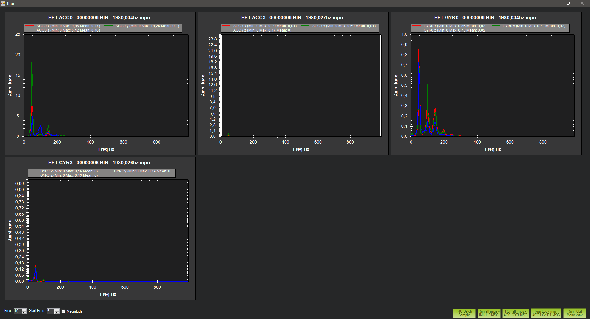
I would suggest first you set the log bitmast as I described above, and also deal with the vibrations. There is significant y-axis vibration that should be addressed before you try to get too far with the tuning. Since it’s only Y, have look to something loose like landing gear or camera mount. Maybe there’s wires pulling on the flight controller in one direction.
To what value is it desirable to reduce the amplitude of the IMU spectrum?
In the online tool, I can adjust the filters so that the amplitude is reduced by another factor of two.
The Wiki does not indicate what amplitude is considered acceptable.
Based on what parameters in the log can you determine that the notch filter does not have a large phase delay and does not affect the stability of the copter?
How close can the frequency equal to the difference between (INS_HNTCH_FREQ - INS_HNTCH_BW) be to the value INS_GYRO_FILTER=20 when setting up a harmonic filter?
Is it possible to set INS_HNTCH_FREQ to a low frequency (eg 15Hz) but not use the first harmonic?
It seems that the operation of the first harmonic at a frequency of 30 Hz is different from the operation of the second harmonic at a frequency of 15 Hz.
If I use INS_HNTCH and INS_HNTC2 simultaneously, do I need the sum (INS_HNTCH_ATT+INS_HNTC2_ATT) not to exceed 40dB? The description of the INS_HNTCH_ATT parameter says that when exceeding 40dB there will be a dip and not a moderate attenuation?
How to understand that a harmonic filter has been applied? In MIssion Planner, I do not see the work of the tuned harmonic filter, I only see the work of the low-pass filter.
Today we went through all the blades and found that two propellers had an imbalance in the mass of the blades, the difference was 2.5 grams.
We sorted the blades by weight and after that the vibrations decreased 10 times in all axes.
Here is the test log file without using the harmonic filter.
Is it necessary to use a harmonic filter in this case?
Tomorrow we want to conduct test flights in the field.
I set the INS_HNTCH_OPTS to 8 so the filter is applied to all IMUs. It is my understanding if you don’t do that the filter is only applied to the primary.
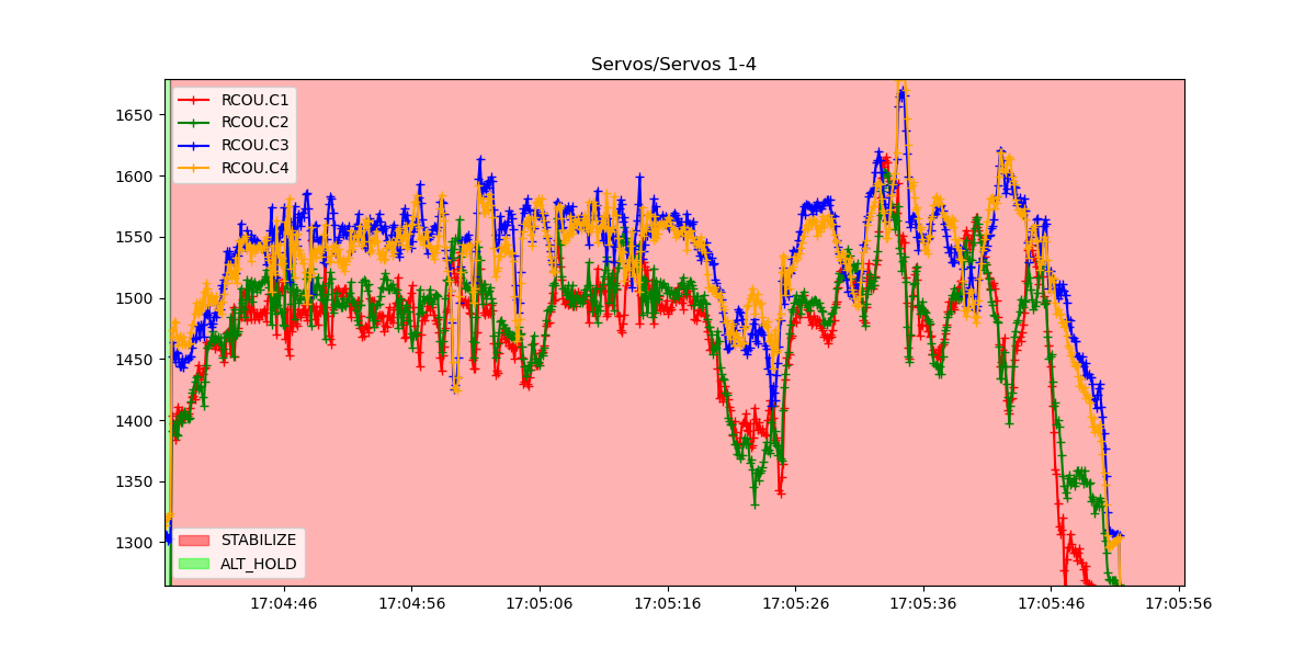
The one thing I did see is there seems to be a torque split between the CW and CCW motors.
Motors 3&4 are working harder than 1&2. This usually means there is a misalignment in the motor arms or a twist in the frame. This one isn’t the worst I’ve ever seen, and you could probably get away with it as is, but if you can get these equal then you’ll get a better tune.
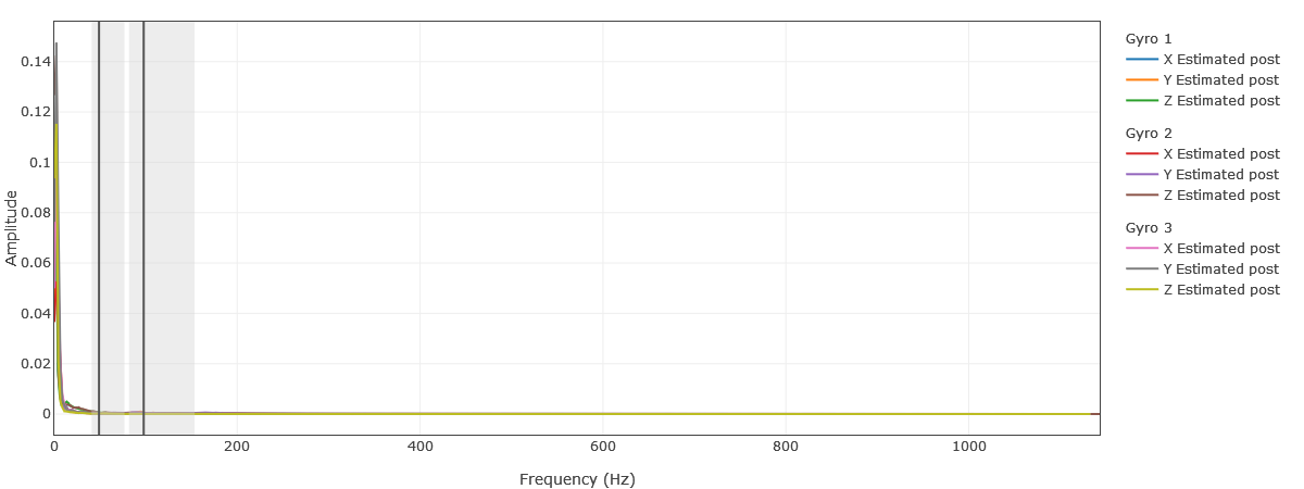
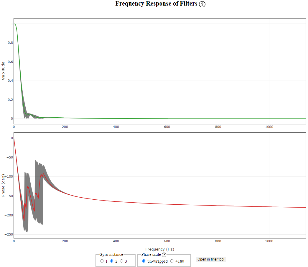
What does the first graph show? How wide can the gray areas be?
Does the second graph show the phase delay? What phase shift is acceptable and what width of the gray zone is acceptable? On what scale is it correct to analyze the second graph, un-wrapped or ±180?
I’m working from what I’ve learned the hard way, and from what I’ve read here. I look for as low value as I can get with the minimum amount of filtering.
Here’s a good resource from the developer of the webtool: