Hello,
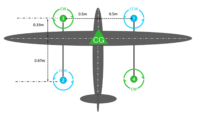
I am trying to better understand how to define motor contributions when developing a custom frame class. I’ve put together diagram of a quadplane here:
This aircraft is setup such that the forward VTOL motors are closer in proximity to the CG compared to the aft motors. If the same motors and props are used, when defining normalized roll and pitch contributions for a custom frame class, would this aircraft be setup like this? (Motor #: Roll, Pitch)
Motor 1: -0.75, 0.50
Motor 2: 0.75, -1.00
Motor 3: 0.75. 0.50
Motor 4: -0.75 , -1.00
and thus implemented into custom frame class as (with the yaw factors being -1.0 and 1.0):
{ -0.75f, 0.50f, AP_MOTORS_MATRIX_YAW_FACTOR_CW, 1 },
{ -0.75f, -1.0f, AP_MOTORS_MATRIX_YAW_FACTOR_CW, 2 },
{ 0.75f, -1.0f, AP_MOTORS_MATRIX_YAW_FACTOR_CCW, 3 },
{ -0.75f, 0.50f, AP_MOTORS_MATRIX_YAW_FACTOR_CCW, 4 },
If smaller motors and props were selected for the rear, as they only require half the thrust contribution to maintain level pitch due to the lever arm, would anything change about the pitch and roll contributions? If not, should the thrust contribution be handled through 6 DoF scripting instead?
Thank you
