Confusion regarding PWM signals seems extremely common here, so I thought I’d take a moment and attempt to provide some clarity.
At its core, pulse width modulation (PWM) is simply a means of conveying information on a digital signal line by varying the duration between times that the line is held high (a digital 1) or low (digital 0).
In many applications, PWM is used to simulate an analog voltage on a digital line by varying the duty cycle, as depicted here:
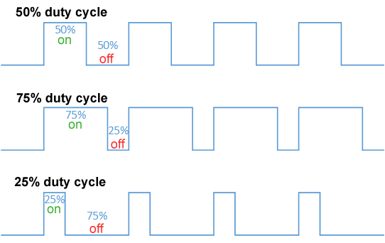
The PWM frequency in these applications is derived by measuring the time between rising (or falling) edges. The duty cycle can be varied regardless of frequency, and it’s up to the use case to either read the signal digitally or filter it appropriately for use as an analog approximation.
Arduino/microcontroller hobbyists are most familiar with this type of PWM signaling (likely the root cause of the confusion). The default frequency for many of these controllers is 488Hz, and the resolution is often 8-10 bits (duty cycle resolutions of under 0.5%).
HOWEVER!
Most times when ArduPilot users speak of PWM, we are referring to a very specific protocol used by servos and ESCs, most commonly in RC hobby applications.
In this case, PWM is indeed the correct terminology, but the variation in pulse width is not duty cycle based. Rather, the frequency is typically 50Hz (20ms period), and each pulse varies in duration corresponding to a desired servo position (typically 1000-2000µs, with 1µs resolution), as depicted here:
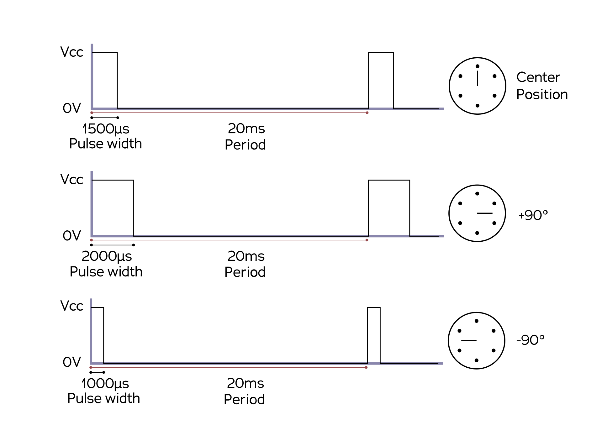
This explains why servo input values are given in µs, and if you compare the first to the second image, it should be apparent that the two PWM signal types described in this topic are not interchangeable at all. Servo PWM signals do not vary enough in duty cycle to be useful as analog voltage approximations.
THE PROBLEM
Most hobby servos and ESCs expect a servo PWM signal as depicted in the second image. These devices are supported by default in ArduPilot autopilots.
However, some motor controllers (particularly brushed motor controllers) have an input labeled “PWM.” Often, that input expects a duty cycle based signal as depicted in the first image. Others (such as Sabretooth controllers) can be configured to operate like ESCs and use servo PWM signals.
It is imperative to read the datasheet or user’s manual for your controller and understand what input signal is expected.
The good news is that ArduPilot can be configured to output duty cycle based PWM for use with brushed motor controllers:
Brushed Motors — Copter documentation (ardupilot.org)
Brushed Motors — Rover documentation (ardupilot.org)
As described in the wiki, some care must be taken when configuring ArduPilot for use with these controllers. STM32 pin grouping can present some challenges when configuring the autopilot for use with multiple types of outputs, and you may find that you end up with fewer useful output pins than you would otherwise have with a different (servo-based) output configuration.