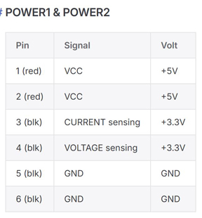
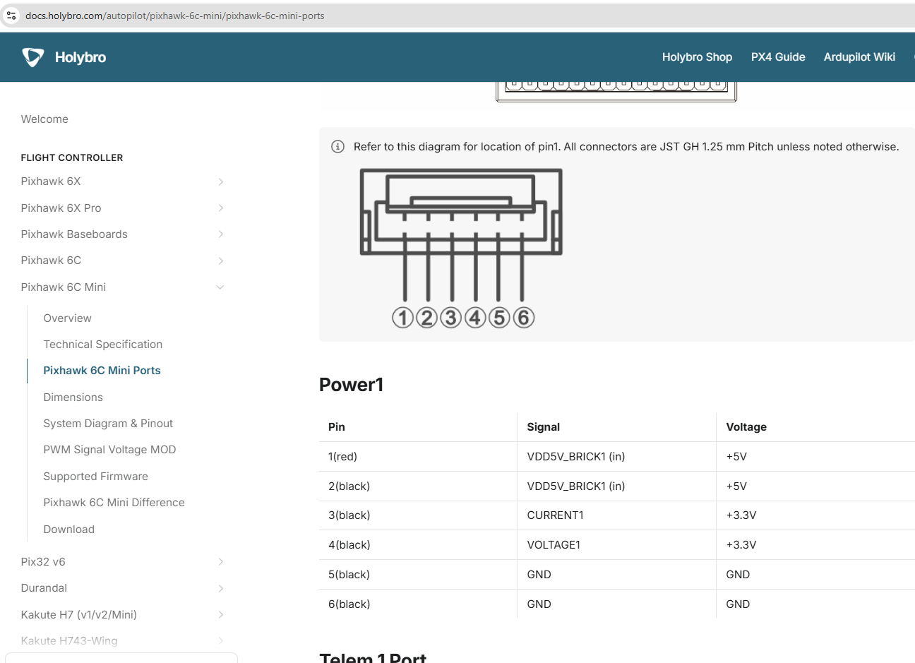
Is there information available about the voltage and current sensor pins on the Power-1 and Power-2 connections?
Many 4-in-1 ESC’s have a pad defined as “current”. I’m curious to know if there’s anyway this output from the ESC can be fed to the Power-1 or Power-2 current sensor pins.
I’m guessing that the Power-1 and Power-2 sensor pins for voltage are not designed to accept direct battery voltage. I’m curious how battery voltage has to be “conditioned” to be accepted by these pins on these ports.
I’m guessing here that these Current and Voltage sensing pins are specified by an original Pixhawk/APM architecture - and have been widely adopted.
And I’m guessing that Ardupilot uses this and addresses these pins when “analog” is selected as the battery monitor. (I have a faint recollection of one of these pins being referred to as “pin-14” - perhaps from an earlier APM schematic.
Anyway - the main thrust of my query is to what extent can we rely on ESC telemetry for voltage and current telemetry - and in particular, for FETTEC esc’s.
As an aside - some flight controllers no longer use these two pins for analog signals for current and voltage data. Instead, these pins accept digital signals new current sensors that have digital signals for current and voltage data.
If you look at the Holybro website, you’ll see that Holybro is now making a note about the type of current monitor required for their flight controller models.
The voltage and current information contained in the FETtec oneWire digital telemetry is accurate, but a bit noisy.
The analog current output is scaled to 3.3V and you can use a voltage divider to create a 3.3V scaled battery voltage measurement. Then input these two into the power connectors. That will give you redundancy.