Mostly good news here, and thank you to everyone that has come before me, including the developers and forum contributors Yuri and ktrussel in particular.
Last summer - RTK YAW-heading and Position - Fix Status - I got GPS YAW to cooperate, but had some other issues (Rover 1 had a gearbox failure (that I “fixed” but has returned) while Rover 2 experienced battery failure I couldn’t address in time)
I replaced the batteries on R2, and upgraded to Rover 4.2 last month.
One important take away while fighting to get YAW to work again - I think the key step I kept dodging was to reboot the flight controller once in a while. I reconfigured all sorts of things, including adding distance between the GPS antennas, and was continually frustrated trying to get YAW to cooperate again - and then I rebooted, and ah-hah.
While I have an ArduSimple board with a Lite piggybacked on top, I’ve begun following Yuri’s advice to just let it auto configure, which includes the RTCM packets going through the FC.
I measured and set the GPS offsets to the best of my ability. It’s configured to use only the MB GPS - I haven’t yet, as suggested in last year’s thread, configured a script to stop when the MB drops out of Fixed. Generally, it’s staying in RTK Fixed unless the fixed base goes off-line.
EK3_SRC1_YAW,2
GPS_AUTO_CONFIG,1
GPS_AUTO_SWITCH,0
GPS_BLEND_MASK,5
GPS_COM_PORT,1
GPS_COM_PORT2,1
GPS_MB1_TYPE,0
GPS_MB2_TYPE,0
GPS_POS1_X,-0.435
GPS_POS1_Y,0
GPS_POS1_Z,0
GPS_POS2_X,0.165
GPS_POS2_Y,0
GPS_POS2_Z,0
GPS_PRIMARY,0
GPS_RATE_MS,200
GPS_RATE_MS2,200
GPS_TYPE,17
GPS_TYPE2,18
This works just fine, even with the Lite board piggy backed on top - the UART1>UART2 connection is just ignored (I believe the alternate auto configuration is to use two big ArduSimple boards and UART2 on both for direct communication)
The “big board” is my MB, the Lite is the Rover.
I can send RTCM corrections via MavLink from MissionPlanner and things work just fine - though with a 57,600kbps link, things are a little slower than I’d like due to congestion, and sometimes Missions fail to transfer (again, I assume congestion).
After proving that worked, I stopped sending the RTCM via MavLink, and instead I have the USB port of the ArduSimple board connected to my companion computer, a Raspberry Pi 3.
The Pi has two wifi connections (internal, and an external) and I’ve blanketed the property with wifi relays here and there. The dual adapters are intended to provide overlap in coverage (I do need to figure out how to have two wpa_supplicant files, one per adapter with non-overlapping AP lists)
From the RTKLIB package, I use “str2str” to acquire the RTCM stream from my fixed base and pipe it to the USB (/dev/ttyACM0).
This unburdens the 57.6k link.
The Pi also runs Mavproxy (telem to USB-Serial) so I can use a UDPCL connection.
(As I look into adding mavlink-router into the mix to accommodate changing IPs as the Rover wanders the property, I’m wondering if I should use Mavlink-Router on the Rover rather than MavProxy. There seems to be some overlap, with Mavproxy/mavgateway being a less featured implementation)
(The Pi has a Pi Camera with a long ribbon cable - the same RFI that forced me to abandon the compass for GPS YAW causes problems with the Camera feed)
I tuned the throttle, steering, and so forth per the documentation, and I’m thus far happy with the results.
ATC_ACCEL_MAX,4
ATC_SPEED_D,0
ATC_SPEED_FF,0
ATC_SPEED_FLTD,0
ATC_SPEED_FLTE,10
ATC_SPEED_FLTT,0
ATC_SPEED_I,0
ATC_SPEED_IMAX,1
ATC_SPEED_P,0.1
ATC_SPEED_SMAX,0
ATC_STOP_SPEED,0.1
ATC_STR_ACC_MAX,720
ATC_STR_ANG_P,2
ATC_STR_RAT_D,0
ATC_STR_RAT_FF,0.15
ATC_STR_RAT_FLTD,0
ATC_STR_RAT_FLTE,10
ATC_STR_RAT_FLTT,0
ATC_STR_RAT_I,0
ATC_STR_RAT_IMAX,1
ATC_STR_RAT_MAX,350
ATC_STR_RAT_P,0
ATC_STR_RAT_SMAX,0
ATC_TURN_MAX_G,0.6
NAVL1_DAMPING,0.85
NAVL1_PERIOD,5
NAVL1_XTRACK_I,0.02
TURN_RADIUS,0.9
WP_OVERSHOOT,0.001
WP_PIVOT_ANGLE,0
WP_PIVOT_DELAY,0
WP_PIVOT_RATE,300
WP_RADIUS,0.100584
Even though I built a skid-steer zero-turn rover, my turning radius is set to 0.9 and Pivot turns are disabled - while the rover can spin 360s just fine, the trailer it tows doesn’t appreciate that.
With RTK, you can see I locked down my WP radius and overshoot to what I think are about the lowest values it’ll take.
This works.
I have a Maxbotix I2C Sonar, and a SmartFly TF-Luna LIDAR via I2C.
I had both setup as range finders and got figures back.
RNGFND1_ADDR,16
RNGFND1_FUNCTION,0
RNGFND1_GNDCLEAR,10
RNGFND1_MAX_CM,300
RNGFND1_MIN_CM,10
RNGFND1_OFFSET,0
RNGFND1_ORIENT,1
RNGFND1_PIN,-1
RNGFND1_POS_X,0.17
RNGFND1_POS_Y,-0.17
RNGFND1_POS_Z,0
RNGFND1_PWRRNG,0
RNGFND1_RMETRIC,1
RNGFND1_SCALING,3
RNGFND1_STOP_PIN,-1
RNGFND1_TYPE,24
RNGFND2_ADDR,112
RNGFND2_FUNCTION,0
RNGFND2_GNDCLEAR,10
RNGFND2_MAX_CM,700
RNGFND2_MIN_CM,20
RNGFND2_OFFSET,0
RNGFND2_ORIENT,0
RNGFND2_PIN,-1
RNGFND2_POS_X,0.2
RNGFND2_POS_Y,0.17
RNGFND2_POS_Z,0
RNGFND2_PWRRNG,0
RNGFND2_RMETRIC,1
RNGFND2_SCALING,3
RNGFND2_STOP_PIN,-1
RNGFND2_TYPE,2
I couldn’t get object avoidance to work until I learned this tid-bit.
You have to set PRX_TYPE=4 to use your range finders as proximity sensors.
Unfortunately, after enabling object avoidance and setting PRX_TYPE, the Rover started wandering about like a drunk sailor and refused to run the mission that worked moments ago.
MissionPlanner, under the Control-F menu, has Proximity UI (second column, near the bottom) that shows you what obstacles are being detected, and mine was reporting an obstacle right in front (0.3m) almost all of the time.
I wasn’t able to finish debugging the combination of range finders to find one that was going to work.
Instead, I enabled Fences. I believe KTRUSSEL talks about setting circular fence exclusion zones around trees - bravo!
FENCE_ACTION,2
FENCE_ENABLE,0
FENCE_MARGIN,1
FENCE_RADIUS,10000
FENCE_TOTAL,65
FENCE_TYPE,6
OA_BR_CONT_ANGLE,75
OA_BR_CONT_RATIO,1.5
OA_BR_LOOKAHEAD,2
OA_DB_BEAM_WIDTH,5
OA_DB_DIST_MAX,0
OA_DB_EXPIRE,10
OA_DB_OUTPUT,1
OA_DB_QUEUE_SIZE,80
OA_DB_RADIUS_MIN,0.01
OA_DB_SIZE,100
OA_MARGIN_MAX,0.3
OA_OPTIONS,1
OA_TYPE,1
OSD_TYPE,0
Since the Rover is now the most precise GPS available when it has RTK FIX against my fixed base
(Fixed Base is a Raspberry Pi and another ArduSimple board installed on the chimney. On multiple occasions I logged several days of raw data, then fed it to the Canadian CSRS-PPP - Precise Point Positioning - to resolve the precise location of my GPS antenna, which was then set using UCenter) I manually piloted the rover around the property and set waypoints at every known obstacle (tree, fence)
I then downloaded the plan, and proceeded to add fences and copy/paste the waypoint locations into the circular or polygon fences.
(Is there a better way to do this? Editing the saved files in notepad isn’t much faster, though perhaps a spreadsheet would make this easier)
With the fences in place, I could run a mission and it would go around the obstacle, even without the rangefinder/proximity sensors - it’s just not able to adapt to changing environments.
Still, substantial progress.
I did learn, I believe, that the OA_MARGIN_MAX when used with a Fence is from the Fence boundary.
I have mine set at 0.3 or roughly 1’.
That means for a small diameter tree, I can set a circle fence with a 0-radius, or for a larger tree I use a larger radius - but there’s already a 0.3m margin built in.
I thought I had learned whether the FENCE_MARGIN matters in this case, but now I don’t remember. ![]()
This does present a slight problem if, like I did, you drive the rover around to mark your fence positions - I can’t send the rover around the “find my fences” mission because it would now be within 0.3m of the fence.
Has someone already found the easy solution to shifting my “driven route to become my fence” outward by a certain distance?
For now, I live with the extra margin, but ultimately I’d like the polygon fences to be ~0.3m from where they are. For the trees or clothesline posts, not a big deal, but for following a physical fence line or the creek, I eventually want to get closer.
So, the Mission…
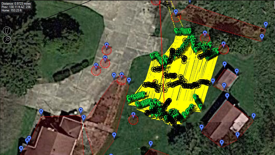
I started with the SimpleGrid. I then manually added a lot more paths, as you can see.
Overall, it works. That is about 150 way points, and covers almost 1 mile to cut that section.
I believe I started with a 3m width on the routes, and maybe I needed to go wider - again, I’m artificially inflating my turning radius to allow for a trailer, but you can see it likes to turn and then correct back in before proceeding.
ktrussel had some external programs to build some of these mowing routes that I need to revisit.
What I’d like to do is create a SimpleGrid in MP with an appropriate spacing (if I used 3m before, maybe it’s 4m or even 5 - whatever allows it to make a smooth wide U-shaped turn every time) and then create it again, but this time offset the starting point by X meters (fractional).
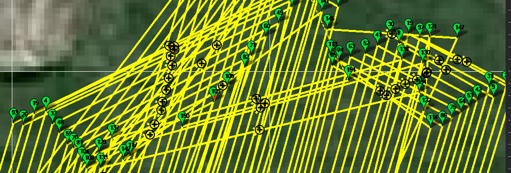
What I really want/need is to run overlapping circles or squares - instead of an up/over/down/over/up/over/down/over, I want to run a up/over/down/back box, then when it goes “up” the second time, it starts offset by 0.3m or so. I could offset the vertical edges but overlap the horizontal, or offset both, but ultimately making “large” circular routes that overlap each other in a consistent manner.
That’s what I attempted to hand draw.
For completeness, I might run a “vertical” overlap and then run a similar route but with a “horizontal” overlap to cover any strays.
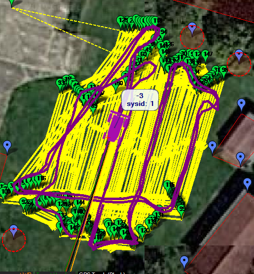
Still, aside from the tedious attempts to manually make the plan, I’m able to consistently run my mission and get overlap even with only a 14" wide path.
Recapping the build list.
Used WheelChair
2x55AH 12V deep cycle batteries
Master on/off, safety kill switch
Pixhawk 1.
RoboClaw 2x30 motor controller (Mistake! Works fine driving around, but when towing it will overheat and goes into failsafe - I need to move up to the 2x45 or 2x60)
ArduSimple and Lite boards
Raspberry Pi 3, Pi Camera, RT5370 USB Wifi, USB to Serial (to TELEM)
24V to 5V regulated supply for RPi
Missing in the video is the 2x20w solar panel roof, and a PWM controller - calculations say it would take a week to recharge this way.
Simple pin hitch. New 14" wide reel mower converted with a tongue - handle retained for now for ballast.