24/01/2017
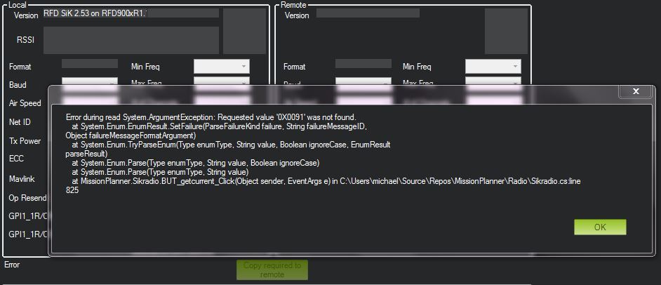
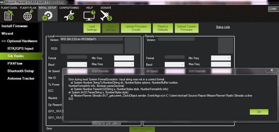
Mission planner could talk with RFD 900 and RFD 900+ diversity radio modems without problem. It isn’t the case with the latest RFD 900x.
Apparently it is due to a little change in the way the 900x needs to be “talked to”. In the mean time I have useless modem sets
By the way I did try to change some parameters on the RFD 900X, such as S3 that I did set to 65 and stored the value with AT&W. Then rebooted the modem and value was correct.
So it definitely shows this modem to be alive.
Here is AT command and answers from the old hyperterminal:
OK
ATI
RFD SiK 2.53 on RFD900xR1.1
ATI2
131
ATI3
0X0091
ATI4
255
ATI5
S0:FORMAT=32
S1:SERIAL_SPEED=57
S2:AIR_SPEED=64
S3:NETID=65
S4:TXPOWER=30
S5:ECC=0
S6:MAVLINK=1
S7:OPPRESEND=0
S8:MIN_FREQ=915000
S9:MAX_FREQ=928000
S10:NUM_CHANNELS=20
S11:DUTY_CYCLE=100
S12:LBT_RSSI=0
S13:RTSCTS=0
S14:MAX_WINDOW=131
S15:ENCRYPTION_LEVEL=0
S16:GPI1_1R/CIN=0
S17:GPO1_1R/COUT=0
R0:TARGET_RSSI=255
R1:HYSTERESIS_RSSI=50
ATI6
silence_period: 252
tx_window_width: 6354
max_data_packet_length: 249
packet_latency: 126
ATI7
L/R RSSI: 0/0 L/R noise: 79/0 pkts: 0 txe=0 rxe=0 stx=0 srx=0 ecc=0/0 temp=28
dco=0
ATS0?
32
ATS1?
57
ATS2?
64
ATS3?
65
ATS4?
30
ATS5?
0
ATS6?
1
ATS7?
0
ATS8?
915000
ATS9?
928000
ATS10?
20
ATS11?
100
ATS12?
0
ATS13?
0
ATS14?
131
ATS15?
0
ATS16?
0
ATS17?
0
ATS18?
ERROR
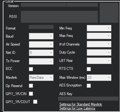
With “Beta updated” version of Mission planner, it does connect to the modem. Thank you Michael. below is a screen grab of the successful connection.
I’ll try to connect to the airframe when daylight shows and will try CPPM as well. Will measure latency on CPPM with a scope.
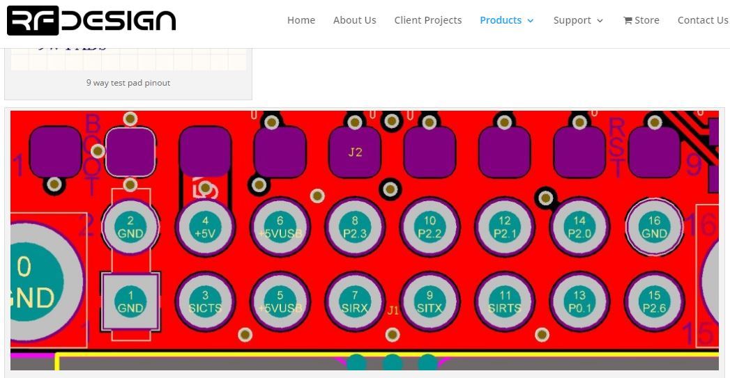
If you look at the setup screen, I would think depending if you set GPI1R/C in or out the CPPM function would be enable.
This is, however, a question for Seppo at rfdesign…
I am attempting to use the RFD900x to passthrough PWM or PPM…
From other discussions it seems that “GPI1_1 = R/C In or R/C Out” refers to RFD900x GPIO Pin 15 (or P2.6). Is that correct? I was trying to use PIN 13 (of P0.1)…
Some clarification on the setup would be great.
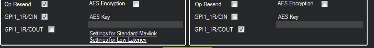
I am assuming that I setup
GPI1_1R/CIN checked at the transmitter end of the link and
GPI1_1R/COUT checked at the other end of the link.
Do I need to setup the radio with AT commands to make the pins at the transmitter end Inputs or is the PPM function separate from these settings?
Any updates on the testing of the 900x?
I am really interested in knowing if the latency of PPM is good enough as well as reliability.
I already have a couple of 900+ but they are incompatible with the 900x so im not sure if it is worth it.
Thanks for your comments.

 Thank you Michael. below is a screen grab of the successful connection.
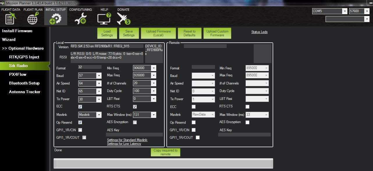
 Will you use CPPM capabilities of the RFD900X as well?