PPM recognition

Hello, I connected Turnigy 9xv2 receiver --> PPM encoder --> PIXHAWK RCIN port. But the pixhawk cannot recognize the signal, I measuered the PPM encoder output whith oscilosscope and I get this:
http://s8.postimg.org/gofsmas39/scope_8_csatorna1.jpg http://s12.postimg.org/5fyuk9ybh/scope_8_csatorna2.jpg

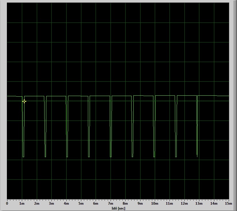
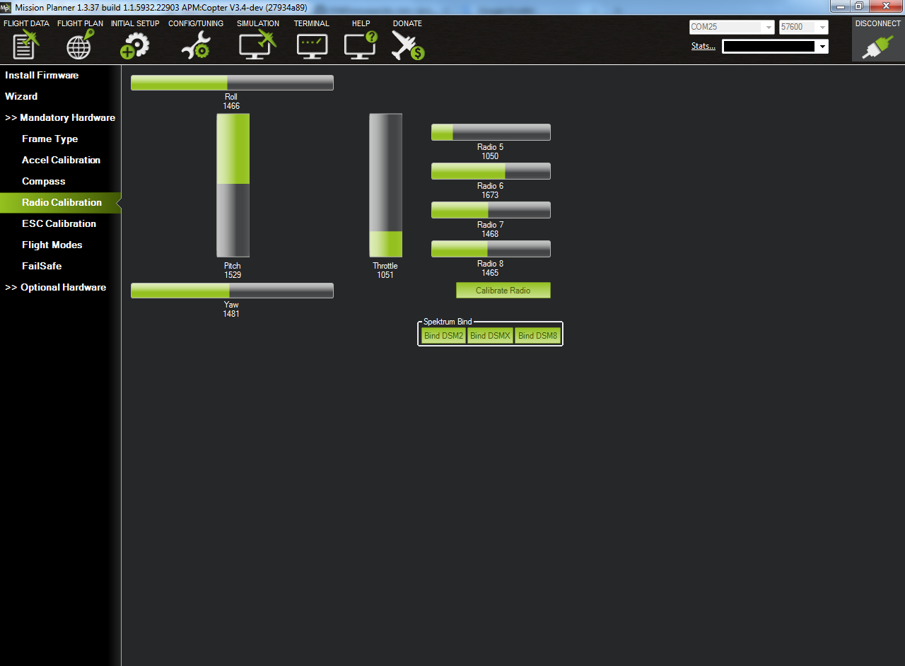
I think this PPM - SUM signal is quite narrow as it shoud be (and this is the problem), but when I move with knobs on turnigy radio the signal is changing. Does anyone know what I should change in the code of arducopter to recognize this signal?

I would bet that you have not connected the ground of the receiver, the PPM encoder and the Pixhawk together.

They need to be in the same voltage level: your Pixhawk ground.

Dont bet or you lose. I connected it together, it still not going :frowning:

I may have had a brain fart:

If I recall correctly, the PPM signal does not have long low-times. It does not look like many juxtaposed PWM signals.

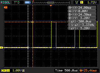
Each channel is separated from the next one by what you see as a dip in the voltage. Actually, that should be a low level lasting 300us if I remember right.

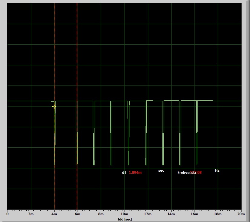
What is the low time of each short pulse? It is not clear in your picture, but it is not impossible that it lasts about that long.

So, concluding, I would say that in second glance, I don’t see anything wrong with this PPM frame.

Thank you for the answer, I attach some photos of the PPM signal.

All channels is in center:


Channel 1 minimum:

channel 1 maximum:

Pulse width:

Iam used sound card as oscilloscope.

I was trying to find a specification for the pulse time for the PPM stream.

This is the PulsePositionLibrary for the Teensy microcontroller, which I have used in the past. By default, it has an 100us TX_PULSE_WIDTH.

Wikipedia talks about 300us.

Yours seem like 150us and I don’t believe it should be a problem.

When I get to the lab on Monday, I’ll try to get a screenshot of the PPM output of my ezUHF 8ch diversity receiver for comparison.

PROBLEM SOLVED

Thank you for the help, I modified in file:

github: drv_hrt.c

Line:

_#_define PPM_MIN_PULSE_WIDTH 200

value 200 to 20 (with value 30 is little uncertainity).

In addition with simple 2 resistors and with one transistor I inverted the signal:

Then I recompiled the code, uploaded to pixhawk and with this two modifications it going fine. Now, I am very happy :slight_smile:

Iam still curious to your PPM signal if you could upload. Thank You!

So it seems that your PPM generator was making a MIN_PULSE_WIDTH smaller than 200 (as we noticed) and it wouldn’t get detected.

Why did you invert the signal, though? Was it necessary to do that?

BTW, are you using the PX4 or APM stack?

Yes it is necessary (I dont know why).

This is on Pixhawk.

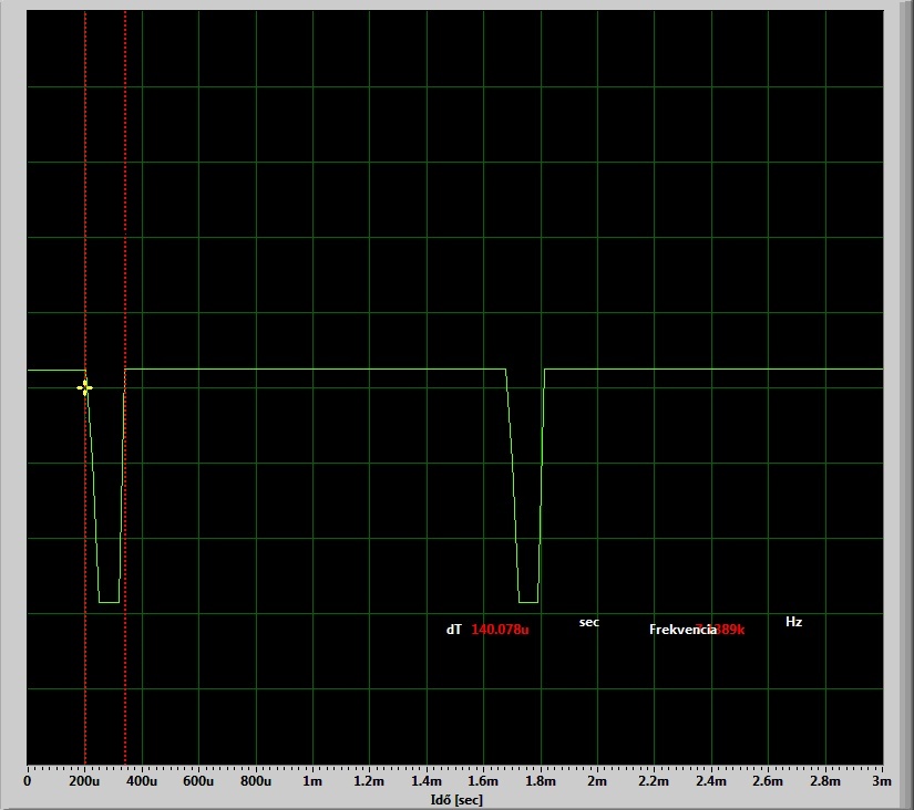
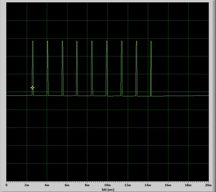
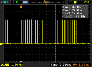
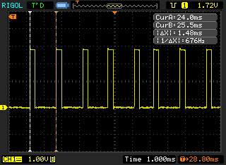
Here are some PPM snapshots from my ezUHF 8ch diversity receiver, as promised, but belatedly delivered.


As you can see, it has an 24ms frame and a 300ms pulse time.