But on the MP my rover tracks backwards/incorrectly/weird. So to make my rover track almost correctly, I’ve made the following two changes to original POZYX Arduino Pixhawk sketch:
Is this something that is fixable in the MP coding or ???
Thanks
RoboBill
Update: I now have the anchors in a rectangular shape, but still have incorrect paths.
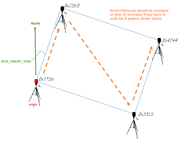
According to the Loiter Arduino sketch, the anchor ID values increase according to the “N” pattern. Are the anchor ID values translated to decimals to determine order? In the sketch, that doesn’t seem to be the case.
Is this 3.2 forum the best place to get help with the POZYX & MP interfaces?
Update 2 Switching from EKF 3 to EKF 2 seems to make things work much better.
For me… the Y axis is always to the left. As for the Yaw, I first followed the instructions but was never confident of the reading given on the MP. Then I found a web site that gave me headings. Since my POZYX system and its anchors are outside, I was able to determine the correct Yaw within a few degrees.
BTW For some unknown reason, when I switched back to EKF 3, things are working better.
So I suppose you put the position of the anchor 0 and anchor 1 looking on a satellite map in a website like this https://acscdg.com/ and you read the azimuth/bearing from there. It seems ok, but check if it’s coherent with the compass readings.
Or are you setting BCN_ORIENT_YAW to the bearing from anchor 0 to anchor 2?
For me: #0 anchor is at 0,0 #1 anchor is at x,0 #2 anchor is at 0,y #3 anchor is at x,y
So YAW is from #0 to #2, which is to my left if I’m at #0 looking at #1.
Whats confusing is the anchor ID order. Per @rmackay9, his “N” pattern instructions say #0, #2, #1, #3. But the Arduino code does NOT appear to follow that pattern.
His anchors are declared as:
0x601C, // (0,0)
0x6020, // x-axis
0x6057, // y-axis
0x605E};
If I understand he “N” pattern instructions correctly, it should be:
0x601C, // (0,0) decimal equivalent of 24604… 1st of “N” pattern
0x6057, // x-axis decimal equivalent of 24663… 3rd of “N” pattern
0x6020, // y-axis decimal equivalent of 24608… 2nd of “N” pattern
0x605E}; // decimal equivalent of 24670… 4th of “N” pattern
Not thinking about the x,y axis for a moment, to me seems that in this image the orange text says to place the anchors in the N pattern with ascending IDs (0, 1, 2, 3), so:
  1
          3
0
        2
If this is true, the BCN_ORIENT_YAW is on anchors 0-1 and when you are at 0 and look at 1 you have anchor 2 on your right.
I see your point. And now I’m more confused cuz for as long as I can remember, the y axis was always “to the left” of (or CCW to) the x axis. So for whatever reason, the x axis is now going from 1156 to 256B and the y axis is from 1156 to 3325.
I wonder why it’s set up like that? That may be why I have to tweak my Arduino sketch as noted above. I’ll change per this discussion and let you know.