I’m currently working on a capstone project focused on designing and developing a UAV with Vertical Takeoff and Landing capabilities. Our team plans to create our own aerostructures and airframe. Presently, we’ve configured it as a tri-copter with a rear motor for yaw control and two front motors connected in parallel. We aim to implement a tilt-wing design where all front motors tilt, while the rear motor exclusively controls yaw.
My question pertains to how the rear tilt servo is powered. Currently we have all the motors and escs connected to PM07 Power Distribution Board and the signals for those being connected to the different channels on the I/O PWM Out port on the pixhawk. We are under the impression that the tail servo needs to be connected to channel 7 of the I/O PWM Out port to receive a signal but are unsure how it is powered. Does the servo need to be wired to a BEC or ESC and then connected to the PM07 in order to receive power? Will the servo be powered if we just directly connect the standard 3 pin 0.1" spacing typical on most hobby servo receivers directly to channel 7 of the I/O PWM Out of the pixhawk ?
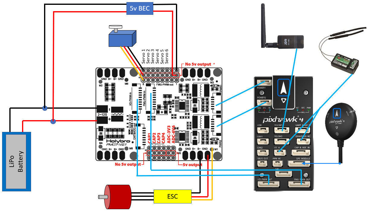
The reason we are asking this is because we have seen some documentation that says the servos for the control surfaces need to be connected like to the PM07 servo rail using a BEC or ESC that is connected to the Battery like the picture below. Is this the same way that we need to connect the tail servo?
Any help would be greatly appreciated