Not sure if anyone has the CUAV CAN PMU (I have like 4 )
However I have found, what I think is a design flaw.
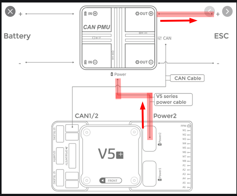
In normal mode, powering up the PMU with the battery supplies the ESC, Gimbal and VTX (for example) with power. However what I have found is that if you connect the Flight controller to USB ONLY, for reading the logs or configuration changes, the voltage from the Flight controller is back fed through the system.
The red line follows the 5V power when the Flight Controller is powered by USB ONLY
The real issue here is that if I leave everything connected I CAN NOT power up my flight controller via USB due to the current draw on my computer’s USB port. This is mainly due to the fact the my Video Transmitter and Gimble are trying to power up, but lacking due to only 5V and no available current to speak of
In the mean time when I need to make changes or read log files I unplug the power feed line from the PMU to the Flight Controller. I have ordered a couple of Schottky Barrier Diodes that I am going to place in the 5V power lines between the PMU and the FC.
Just wanted to make sure if anyone else has this PMU they are aware of this issue.
I am in contact with CUAV and we are trying to work through it to find out what changes need to be done officially
I have no comments on that Particular GPS. I had one test with on CAN. It worked fine, but then I sold it. I am a CUAV exclusive user, both CAN GPS’s and Flight Controllers.
I am sure someone with extensive experiences with the Here2 GPS could better answer your questions
Just an update. In speaking with CUAV enginnering last night, the problem was identified and they are working on a V2 for the CAN PMU. I should be available in a month or 2
Isn’t this completely expected behavior? If your power source is not capable of handling the load, such as a 500mah USB connection, nothing can be expected to function properly. This goes for any flight controller.
Matt the issue here is the PMU is missing a diode barrier to prevent the 5V from the FC from leaking back to the output side of the PMU.
This only applies to when you power the FC from USB to read the logs or make config changes.
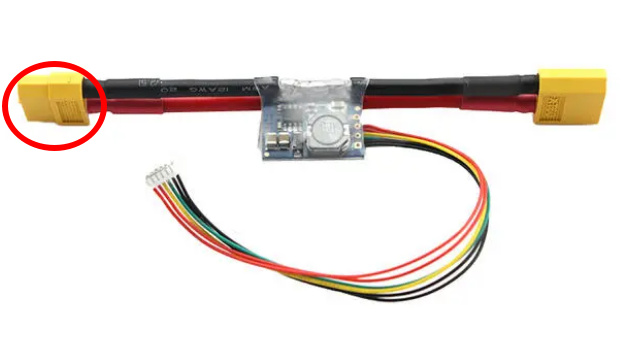
For example, using the following power unit
If the JST cable in plugged into to the flight controller and then powered up via USB only, I do not expect to see +5V present at the end circled in red. This is due to a back feed prevention circuit in the power unit.
This is what is missing in the first run of the CAN PMU
I was thinking about this, and it sounds like a design fault in the V5+ flight controller (maybe carrier board??) rather than the CAN PMU.
My opinion is:
5V from either USB or Power1 shouldnt be feeding 5v out Power2.
Nor should 5v feed back out Power1 or USB if Power2 is powering the carrier board.
Any power input should only be feeding the flight controller itself and any accessories plugged in the FC.
What if you unplug the CAN cable? is the 5V going down that?
Your Schottky diodes in the power wires may fix it if those power wires are actually where the current is going. Diodes in the CAN cable might not be suitable - is 5v wired up in the CAN cable and if so is it even needed?
EDIT: actually looking at the schematic of the carrier board, it looks like all the 5v inputs are just paralleled up together. There are current limiting/power management chipsin place but it’s unclear if they’re connected to specific PM inputs or just providing two separate 5V managed outputs from a common 5v input.
EDIT2: looking again, it looks like the 2 PM inputs do actually go through 2 separate power management IC’s. CUAV have done their job there!
So maybe just the USB and CAN 5v is an issue???
Shawn the problem lies in the power wire from the PMU to the FC. That is where power is back feeding. Although the 5V is present in the can connection that seems to be isolated. Unplugging the power lead from the FC prevents power from feeding back to the PMU where it leaks out when powering the FC via USB only.
I have a PH4 mini that I am going to test tomorrow and see if that energizes 5v on the power line to the current sensor board. I assume it will.
I will say that using the standard power board that comes with the Nano and the V5+ this problem is not there. I spoke with CUAV the other night and they were fully aware of the issue which spawned a PMU V2 redesign.
I do applaud CUAV for finding this issue quickly though.
 )
)