Yesterday I installed a MAUCH HS series 100A current sensor. I have a Tarot 650 Sport frame. FC is a Pixhawk 2.4.6 running the latest stable AC firmware.
The previous sensor was the ubiquitous 3Dr style rated for 6S and 90 Amps.
The MAUCH sensor is mounted between the rail mounted battery tray and the lower frame plate.
Pixhawk is mounted on a vibration damper mount that is attached to the top plate. The Pixhawk is approximately 50mm above the current sensor.
The M8N GPS/compass puck is mounted on a fiberglass canopy. The GPS puck is approximately 85mm above the MAUCH sensor.
I am using a Taranis X9E running Flight Deck telemetry
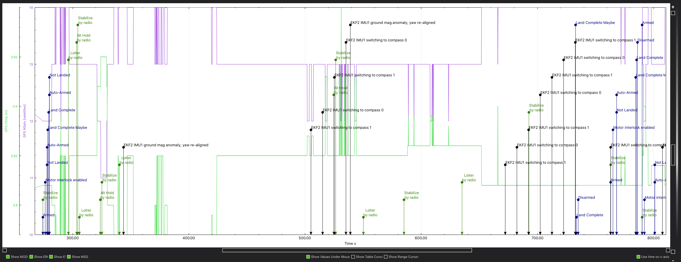
Prior to installing the MAUCH I have had NO issues with either compass. I did a test flight this morning and after about 5 minutes or so of hovering I switched from Stabilize to Loiter and shortly there after my radio started “pinging”. I glanced down at the display and saw “EKF2 IMU1 ground mag anomaly, and EKF2 IMU1 switching to Compass 1.”
It switched back and forth between 1st and 2nd a few times. Mag 2 (Internal LSM303D) is pretty noisy. At least compared to the external one. Do you have a log from before the Mauch sensor was installed to compare?
The only difference I can see in the Mag is the slightly greater separation of the Y
But curiously there is nothing from your mag’s that I can see causing the EKF to go off like that.
The only other thing in the logs that is different and shows ‘something’ happening at the time of the EKF errors is the GPS.
But compared to the previous flight the GPS values are much better, just more variance.
But they don’t seem significant enough to be an issue.
There is slightly more noise on the Vcc and Servo rail but the noise level is so low I cant see it causing issues.
So no ‘AHA’ moments, just letting you know what I could see which wasn’t much.
Multiple compasses seem to have more issues now, maybe try just the external compass and see if the issue arrises.
The Desired to actual roll/pitch/yaw is pretty noisy and the hard working motors are probably generating most of the noise that we doo see.
I have the internal compass disabled, but its been nasty raining all day long. I dug through the flight logs and I can see a HUGE divergence between the internal and external compass that is caused by going from Armed to Hover Throttle, so the problem is coming from the power system.
Yeah, that’s what I’m thinkin’. I’m going to set up for it tonight and run it first thing in the morning, and if it’s not raining (fingers crossed) I might be able to get a test flight in…
I ran CompasMot and did a short test flight. I looked at the mag reading in the data flash log, and taking into account that the external mag is inverted, the axis plots are on top of each other with no throttle induced divergence.
I was thinking about the change in mag related interference and although I haven’t actually done any tests, the idea of the Hall effect is that it is using a magnetic field to measure a value.
So it might be logical to think that hall effect sensors might generate more magnet interference.
The flight only lasted long enough (just a couple of minutes) to get some mag data.
We’re looking at snow for tomorrow so its gonna be a day or two before I can make a longer flight.
As for the Hall device, I believe it is measuring the strength of the magnetic field generated by main battery current flow. I suspect that the wire size (10ga) and length generated a field that was considerably stronger than the field generated by the 3DR style battery monitor I was using previously.
Fortunately it appears that running CompasMot did the trick.