I have watched the video at http://ardupilot.org/dev/docs/porting.html and learned about the migration of the project to ChibiOS and its simplification regarding porting to new hardware.
I’ve made a hwdef.dat file for the board here: stm32F4ve/hwdef.dat
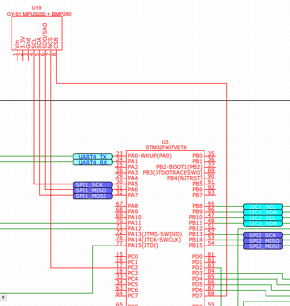
The plan was to also use stm32f103 for FMU_IO in the long run, however for now I want to focus on the main board. GY-91 mpu9250+bmp280 board is to be primarily used. Also “NEO-M8N Ublox GPS Module w/Compass +GPS for APM2.8 APM2.6 Pixhawk”.
I have tried to retain the fmu_v3 pinout as much as was possible.
However this board has build in Flash chip on SPI3, which is one of the major deviations so far.
Also, I am confused regarding the PPM/SBUS input pin, I lean towards PC7 which is also USART6_RX but that was giving me errors.
The main challenge I am facing right now is that this board has only 512kb of memory, and my successful compile ends up being 988024.
During compilation of 506 steps/files I have noticed that it compiles a lot of things I wouldn’t necessary need.
My question is: is it possible to disable modules/features to lower the size to ~500kb?
I have added those STUB_OUT lines as well as all the “define xyz disable” lines to my hwdef.dat file.
./waf clean
./waf configure --board stm32F4ve
./waf copter
and the result is again 784536.
while compiling it still went for 506 files, it did compile all those excluded directories as far as I can see.
Target          Text    Data  BSS     Total
--------------------------------------------
bin/arducopter  654316   864  130284  785464

Build commands will be stored in build/stm32F4ve/compile_commands.json
'copter' finished successfully (1m37.174s)
However it doesn’t look like my edits work.
So far every time it compiles, it compiles everything, including modules/libraries like Airspeed, and all the Sensors variations I am not planning to use.
Does it include everything it compiles into the build file?
Or does it compile everything and selectively picks things it needs for the build file?
I switched my focus onto another board.
STM32F407VG (basically the same chip as in F4Discovery?)
It has 1024k
Although getting a smaller footprint with eliminating modules still interest me.
Attempting reboot on /dev/serial/by-id/usb-ArduPilot_stm32f407vg_31003D001851363135353537-if00 with baudrate=57600…
If the board does not respond, unplug and re-plug the USB connector.
Yes I have connected the VIN and GND to the board and yes the module gets power.
Pinouts
VIN: Voltage Supply Pin
3V3: 3.3v Regulator output
GND: 0V Power Supply
SCL: I2C Clock / SPI Clock
SDA: I2C Data or SPI Data Input
SDO/SAO: SPI Data output / I2C Slave Address configuration pin
NCS: Chip Select for SPI mode only for MPU-9250
CSB: Chip Select for BMP280
Mission Planner does ‘connect’ to the board, but swiftly fails with MAVLink communication.
Mission Planner does not get any GYRO/Accel/Baro readings from the module.
This is what happens in the command line:
Command line output
bps 21 loss 1 left 108 mem 32.3046875 mav2 True sign False mav1 0 mav2 1 signed 0
INFO MissionPlanner.MAVLinkInterface - 1/8/2019 10:37:53 PM 6 ArduCopter V3.7.0-dev (4a6dc0bc)
INFO MissionPlanner.MAVLinkInterface - 1/8/2019 10:37:53 PM 6 ChibiOS: 35ad8a79
INFO MissionPlanner.MAVLinkInterface - 1/8/2019 10:37:53 PM 6 stm32f407vg 003D0031 31365118 37353535
INFO MissionPlanner.MAVLinkInterface - 1/8/2019 10:37:53 PM 6 Frame: UNKNOWN
HUD resize 356 263
HUD 7 hz drawtime 19 gl True
HUD resize 356 261
INFO MissionPlanner.MAVLinkInterface - 1/8/2019 10:37:53 PM 6 Initialising APM
HUD resize 356 267
HUD resize 356 263
HUD resize 356 261
Sensor failure: Baro: unable to initialise driverINFO MissionPlanner.MAVLinkInterface -
Sensor failSensor failure: Baro: unable to initialise driver
INFO MissionPlanner.MAVLinkInterface -
Sensor failSensor failure: Baro: unable to initialise driver
INFO MissionPlanner.MAVLinkInterface - 1/8/2019 10:37:53 PM 3 Check BRD_TYPE: Baro: unable to initialise driver
HUD resize 356 267
HUD 3 hz drawtime 37 gl True
HUD resize 356 261
HUD resize 356 259
HUD resize 356 267
HUD resize 356 265
bps 265 loss 1 left 0 mem 43.34375 mav2 True sign False mav1 0 mav2 7 signed 0
bps 21 loss 1 left 0 mem 36.2587890625 mav2 True sign False mav1 0 mav2 1 signed 0
HUD 6 hz drawtime 24 gl True
bps 21 loss 1 left 0 mem 43.2353515625 mav2 True sign False mav1 0 mav2 1 signed 0
HUD 1 hz drawtime 6 gl True
Sensor failure: Baro: unable to initialise driverINFO MissionPlanner.MAVLinkInterface -
Sensor failure: Baro: unable to initialise driver
INFO MissionPlanner.MAVLinkInterface -
Sensor failure: Baro: unable to initialise driver
INFO MissionPlanner.MAVLinkInterface - 1/8/2019 10:37:56 PM 3 Check BRD_TYPE: Baro: unable to initialise driver
bps 83 loss 1 left 0 mem 32.2998046875 mav2 True sign False mav1 0 mav2 2 signed 0
INFO MissionPlanner.MAVLinkInterface - Get param 1 by 1 - got 0 of 1
HUD 1 hz drawtime 3 gl True
bps 21 loss 1 left 0 mem 35.037109375 mav2 True sign False mav1 0 mav2 1 signed 0
INFO MissionPlanner.MAVLinkInterface - 1/8/2019 10:37:58 PM 6 Initialising APM
INFO MissionPlanner.MAVLinkInterface - Get param 1 by 1 - got 0 of 1
HUD 1 hz drawtime 2 gl True
INFO MissionPlanner.MAVLinkInterface - Get param 1 by 1 - got 0 of 1
bps 50 loss 1 left 0 mem 46.5380859375 mav2 True sign False mav1 0 mav2 2 signed 0
INFO MissionPlanner.MAVLinkInterface - Get param 1 by 1 - got 0 of 1
HUD 1 hz drawtime 2 gl True
Sensor failure: Baro: unable to initialise driverINFO MissionPlanner.MAVLinkInterface -
Sensor failure: Baro: unable to initialise driver
INFO MissionPlanner.MAVLinkInterface -
Sensor failure: Baro: unable to initialise driver
Good time of the day lads.
Wanna share the progress of this project of mine.
Here’s the latest flight:
This is not the maiden flight by a long shot, but the first successful flight where all features (manual control, autopilot, and properly smooth GPS position hold) finally worked in adequate capacity.
The action camera is just brutally strapped to the frame of the multi-copter. Smooth video was not part of this experiment. If anything, the recording clearly shows the multi-copter movements in the air.
As already states in previous posts I am using the STM32F407vg Dev board, and not the 407ve one.
It seemed I cannot alter the title of this thread to reflect this fact.
My next plan is to add LSM303D 9 Axis IMU L3GD20 Module 9DOF over i2c.
Unfortunately I am still unable to properly define it in hwdef.dat despite already received help from Gitter/ChibiOS.
Hi, really great work. I have attempted to follow your steps with the black STM32F407VGT6 board (DIYMORE), firmware and bootloader compiles successfully. I am using Ubuntu as a Windows Subsystem for Linux under Windows 10, therefore instead of dfu-util, I use DfuSe from STM and it seems to work. And for the firmware upload, I try to do this from Mission Planner in the install firmware tab. This is where it fails, it keeps giving “ERROR: No response from board” despite numerous attempts and trials (involving recompiling, trying out different jumper configurations, etc).
I am just wondering, is there any proper USB connection between this black STM32F407 board and PC for the firmware upload? Does it have to be the same DFU mode, or is there a specific connection setup? I noticed in your github you showed a resistor between PA12, what is it for exactly?
The bootloader upload worked for me first try, so I vaguely remember the process, but it must have been the dfu-utils, because if it would be a bottleneck for me I’d definitely remember if I spent extra time making it work.
I don’t remember putting the board into DFU mode to upload firmware, only the bootloader. I believe the ./waf copter --upload does that automatically. If your ./waf configure and ./waf copter work in the virtual ubuntu terminal, the ./waf copter --upload should work too.
Regarding the resistor on PA12, I did not have to solder it, I think it was described as a work around in some guide if the computer would not see the board connected. This is where I found the image: https://edoc.pub/diy-more-stm32f407vgt6-boar1-pdf-free.html
All my uploading have been done using directly connecting the microUSB to the computer. Not all cables were suitable though, the cable that worked for me was a premium cable for data transfer.
I did not have to use any ST-Link v2 STM32 or STM8 Programmer usb adapters of any kind at any point.