Pixhawk telemetry with FrSky's R-XSR not working

I can’t get telemetry to work, please help!

Mysetup is:
Pixhawk 2.4.8 with STM32F427VIT6 Rev 3 (2Mb) running Copter V4.5.0-beta2 (FMUv3 firmware)
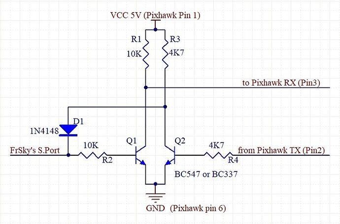
This Yaapu inverter
Taranis X9 Lite S transmitter running EdgeTX 2.9.4
FrSky R-XSR receiver with ACCESS firmware 2.1.8 configured for S.PORT (also tried F.PORT and FBUS configs, no luck)
Also tried flashing D16 (V2.1.0) and D16_FPORT (v2.1.1) nothing

Also tried with an SR8 receiver, same results

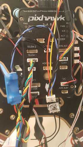
This is how I connected the inverter:

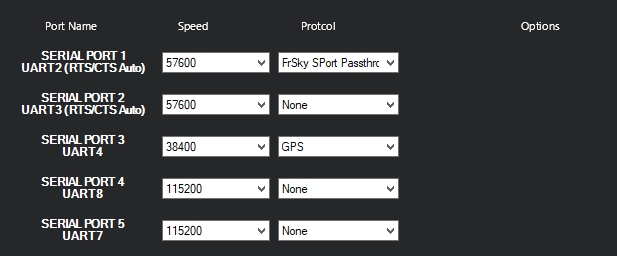
I tried everything in the serial port configuration in Mission Planner (normal, inverted, pullups, change of baud rate, etc…)
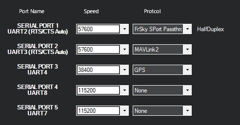
PX_Ports

I even enabled FrSky passthrough in all unused ports (in case my port numbering was wrong, but I know it’s PORT1 because Mavlink2 works there)
I also plugged the inverter in the other ports (2 and 4)
but no matter what I do I can’t get any data from the Pixhawk

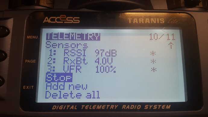
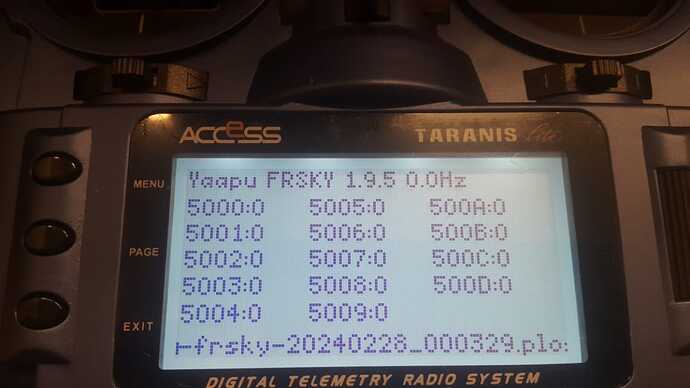
Yaapu debug and YaapuCRSF report 0 in all lines

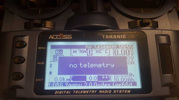
yaapu7 script (installed in screen1) runs but it only displays “no telemetry”

The SBUS signal is ok because I can calibrate the radio in Mission Planner.
The S.Port connector is ok because I can get telemetry from an FrSky GPS ADV connected to the same port
Pixhawk’s Serial 1 is ok because I was able to connect Mavlink2 to Mission Planner and it works…

  • What is the correct baud rate for S.SBUS (or F.BUS or whatever works) telemetry? I’m using 57600
  • Should I invert anything? (I guess not or I wouldn’t need the inverter)
  • Should I enable any pullups or pulldowns?
  • Is that the correct FrSky protocol (using 10) in Mission Planner (also tried another FrSky option in the pulldown)

Please help! Any tips will be appreciated!
Please try once:

SERIAL1_PROTOCOL = 4
SERIAL1_OPTIONS = 0 (NO half-duplex)

Then restart the FC and check the telemetry on the transmitter to see whether telemetry values are displayed.

If this works, SERIAL1_PROTOCOL = 10 can be set and the Yaapu script should run. Re-read the values in the telemetry here too.

I would not configure 2 serial ports for Frsky Sport. One or the other on 1 port.

1 Like

As Dave writes, only set one port for FrSky.

I use the inverter myself, and according to the photo it is connected correctly. However, I don’t have your hardware (SpeedyBee F405 Wing, X8R, ArduPlane 4.4.3).

Can you test with a different FC?

1 Like

Maybe that’s why Copter 4.5x (Beta?) doesn’t work:

Or is SPORT != S.Port? I am not familiar with copter firmware …

I got it working!!! Thank you for the help!

The problem was the “halfduplex” setting as @Reinhard said.
Since the S.PORT is a single bidirectional transmission line I would have sweared it had to be halfduplex… that was the only parameter I never changed :grimacing: and the only reason why I coldn’t make it work before.

This time the problem was that my receiver was left in F.PORT mode (because of the 100 tests I performed before)

About the 4.5.0-beta2 version, that was not the problem.
In fact, my SSD1306 I2C display does not work with OFFICIAL 4.4.4 because the NTF_DISPLAY_TYPE parameter is missing. It works ok with 4.5.0-beta2

sport (mode) is a flight mode, s.port is a type of connection.
And yes, it is confusing but the context usually makes it understandable.

1 Like

I would not configure 2 serial ports for Frsky Sport. One or the other on 1 port.

I know I was asking too much of the STM32, but as far as I know, no telemetry would be sent if no heartbeat/requests are received. I never used the 2 ports at the same time.
Anyways, I got it working now and am using only 1 port in passthrough mode.

1 Like

After wrestling for a while with the connection between an FrSky’s receiver and a Pixhawk, I finally made it work (thank you guys), so here it is.
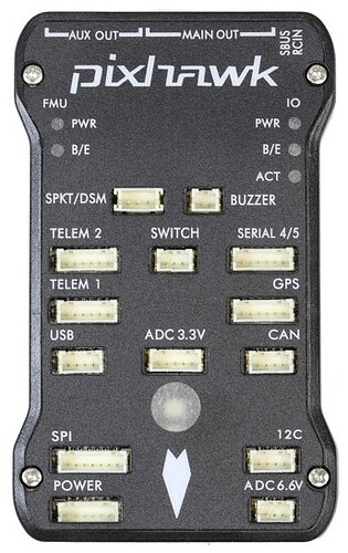
From the Pixhawk side you will need 4 cables connected to one of the free serial ports like TELEM 1

In this photo, Pin 1 of the TELEM port is the one on the LEFT, and the connections you will need are:
1: 5V
2: Pixhawk TX (this is coming OUT of the pixhawk)
3: Pixhawk RX (IN)
4 and 5: not used
6: GND

The circuit is very simple

I’ve seen some implementations of the inverter using a MAX3232. My advice is DON’T DO THAT! The Max3232 is an RS232 level shifter which outputs 13 volts! And that less the 0.7 volt drop in the diode is the signal you will be feeding your 5V receiver; more than 12V!

To build this circuit you will only need:
Small perforated epoxi PCB (pertinax not advised)
(1) 1N4148 diode
(2) 10K resistor (metalfilm recommended because of size)
(2) 4.7K resistor (metalfilm recommended because of size)
(2) BC547 or BC337 transistor
Lots of NPN transistors should work here, not critical but be careful, some NPNs like the 2N3904 have a different pinout (the 2N3904 in this example would point to the other side). I assume that if you change the transistors you know what you are doing.

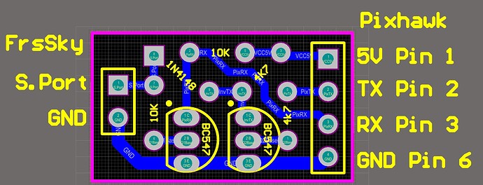
Here is the PCB as a guide:

Yes, some components are installed diagonally, no harm, it’s to save space.

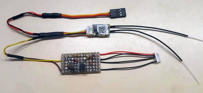
And this is how my prototype turned out:


Outputs from the R-XSR receiver to the inverter are only signal and ground. Since the receiver is also getting power from the Pixhawk via de SBUS connection, the GND cable to the inverter is not even necessary, but put it there anyways (less noise).

Now, in mission planner set Serial port 1 (Telem 1) to “FrSky S.PORT passthrough (OpenTX)”. Clear ALL bitmask bits and set the speed to 57600 baud and reboot the Pixhawk!
My worst mistake here was enabling Halfduplex, which, since the S.PORT is a single bidirectional connection I thought was the correct setting. Since data from the Pixhawk loops back to the RX pin, it requires Fullduplex or it doesn’t work.
PixhawkSerial

Connect the inverter to Telem1, configure the receiver for S.PORT, power up and you should already be getting a lot of telemetry in your radio :wink:.