PixHawk Aux Relay Parameters setting Confusions - SOLVED

dkemxr

here is the filepixhawk param.param (20.9 KB)

That configuration should work. On my bench Pixhawk it does. Some basic troubleshooting:
Does Ch13 go >1800µs when you activate the Tx switch you have assigned?

Connected to the right Output (Aux 5)?

dkemxr

I am not sure what do you mean by, “Does Ch13 go > 1800us”

Its a toggle switch so if I hold it it stays on.

The value prior to click and after click are in enclosed images.

yes, I am connected to Aux Pin 5.

The values that are shown on the screen are in µs is what I mean. Basic RC stuff. Your Ch13 In is activated and showing 2006µs which should trigger the relay output (it’s over 1800µs). I don’t know what else to suggest it’s working for me.

dkemxr
maybe I have a bad voltmeter? :slight_smile: let me figure it out.

Can you directly connect a 3V relay to the pin or do I need a small circuit using a transistor?

I tried the following:

  1. Connected an LED between GND and Signal Pin. LED can turn on @ 1.5V. So it lights up when I flip the switch.
  2. Interestingly, while the LED is connected and if I also connect a voltmeter I get still 1.232 Volts and LED doesn’t light up. How much current Aux Pins can draw?

I have a single ESC BEC (Prop motor) powering one of the Main Out Pins…

So frustrating, I hate to give up…

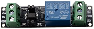
A relay like this type would be suitable.

3V relay

Which Pixhawk do you have?

I have Pixhawk 2.4.8 V3.

I think I have one of these relays lying around somewhere. Let me try them.

That’s the same FC I have on the bench. In fact I tried 2 different Pixhawks (2.4.8 and a 2.4.6) and they both work. I have played around with relay outputs before and never had a problem. Here is one setup if it will do you any good. Parameter file also.


Pixhawk relay test.param (17.5 KB)

1 Like

dkemxr

The culprit was my stupid volt meter. See pics. Its providing wrong readings. I used another one and got 3.333 Volts! what a bummer :slight_smile:

So, does the following description wraps up this topic now?

In Summary, I guess this is what you are saying.

RCx_OPTION = Relay Value

Variable x= Channel number used inside the Tx. It could be any channel from 1 to 16 (If using 16 Channel Rx)

Relay Values are;
28 for Relay 1
34 for Relay 2
35 for Relay 3
36 for Relay 4
66 for Relay 5
67 for Relay 6

Next;

Relay_PINx = Value

Value =50 => Aux Out Pin 1 will act as Relay
Value =51 => Aux Out Pin 2 will act as Relay
Value=52 => Aux Out Pin 3 will act as Relay
Value=53 => Aux Out Pin 4 will act as Relay
value=54 => Aux Out Pin 5 will act as Relay
value=55 => Aux Out Pin 6 will act as Relay

Where x = Relay Pin number from 1 to 6

v1 v2 v3 v4

Hey guys, i have the same problem and already tried everything you suggested but cant get it to work.
I’m using a Cuav V5 Nano, do i need to setup anything different compared to a regular pixhawk?
My Arducopter version is 4.0.3 and no matter what i try, the relay output is not working so far.
My current settings:
RC7_OPTION 28
RELAY_PIN 50
My multimeter reads 4V on all three Aux ports, regardless if they are triggered or not.
Any ideas what i’m doing wrong?

1 Like

Post your parameter file. The Summary above is specific for Pixhawk. That FC doesn’t have AUX ports if you define those as IOMCU outputs as it doesn’t have an IOMCU. But you should be able to get it working on what’s called the 3 Capture Ports.
Try this:
Set BRD_PWM_COUNT to 8
Set RELAY_PIN to 58
Use Capture Port 1 (the 9th channel on the output rail) for the relay.

But Post the parameter file anyway.

1 Like

Thanks a lot, that worked! I should have asked earlier, wasted 6h trying to get it working and with your help it took me two minutes :slight_smile:
Have only had Pixhawks until now, so not really familar with the Cuav.
Here is the parameter file: Parameter.param (17.6 KB)
Have a great weekend!

How did you know it’s Relay_Pin 58 in this case? Couldn’t find any specific information about the Cuav. Am i right to think 59 and 60 are used for the other two capture ports then?

Great! Guess I don’t need the parameter file, I wasn’t sure it was going to work :grinning:.

That’s a very good question. The answer is yes if the BRD_PWM_COUNT is set to 8. Default seems to be 11 in which case all 11 outputs are configured for PWM and relays require they be set for GPIO.
It can be a bit cryptic but the information required to solve this is in the Hwdef.dat (hardware definition) file in the Github repository for your Flight Controller.

The pertinent info is on lines 27-40. If you understand what they are indicating then you don’t need a “guide” just follow the logic!

Around here these days weekends are like any other day but thank you, you do the same!

Thanks, that looks pretty useful.
Yes, it was set to 11 indeed. I already tried lowering it to 8, 6 and even 0 but i never used Relay_Pin 58. I only tried everything from 50-55 on every port :smiley:

One more important point you may use in the future. See on line 5 where is says:
“include …/fmuv5/hwdef.dat”?
That means that the hardware is defined as fmuv5 plus the additions/modifiers in the specific Cuav V5 Nano Hwdef. So for some things you may have to look at the base fmuv5 file.

У меня pixhawk 4 holybro, у меня такая же история, не могу подключить реле, в чем отличие в подключении c cuav?

I have a pixhawk 4 Holybro, I have the same history, can’t connect the relay, what is the difference in connecting with cuav?

Pixhawk 4 you would just configure and use the Aux outputs like any Pixhawk.

current_MP101220.param (17.5 KB)
horus_101120.otx.parm (1.4 KB)


Hi dkemxr,
Great education on a very difficult challenge. Thank you. I still can’t get it to work. All I am trying to do is to assign all six pixhawk aux outputs to relays. I have attached both the param and opentx model file and a screen dump of my logic analyzer output.The OTX file has been renamed to .parm to allow the upload.
I have over 20 hours messing with this and I am totally stumped. I can talk to all 6 aux channels with PWM/servos but only one relay output is controllable. help please.
JP