I am trying to set up a Pixhawk 6C to run ArduBoat, but it will not drive the motors. On the “Servo Output” tab of Mission Planner, I can see that the remote signal is being received, but the motors do not move.
I have been using a smaller servo as a stand-in for the actual one because the boat is quite large and a hassle, and I’ve been inside with no GPS lock, although I’m not sure if that is needed for just getting the motors to move.
Servo rail is not powered through the power connectors on Pixhawks. You need to connect power to the servos externally for example by connecting BEC to spare servo port.
I tried it with an ESC brushless motor (connected directly to the 12v battery) before trying the servo, and it similarly didn’t work. Is it plausible that the motors haven’t been given a sufficient “low” PWM to initialize them? If so, what value needs to be set as the low?
When you say “tried it” do you mean with MissionPlanner motor test?
Defaults of everything should be able to make any typical ESC work or at least show signs of life.
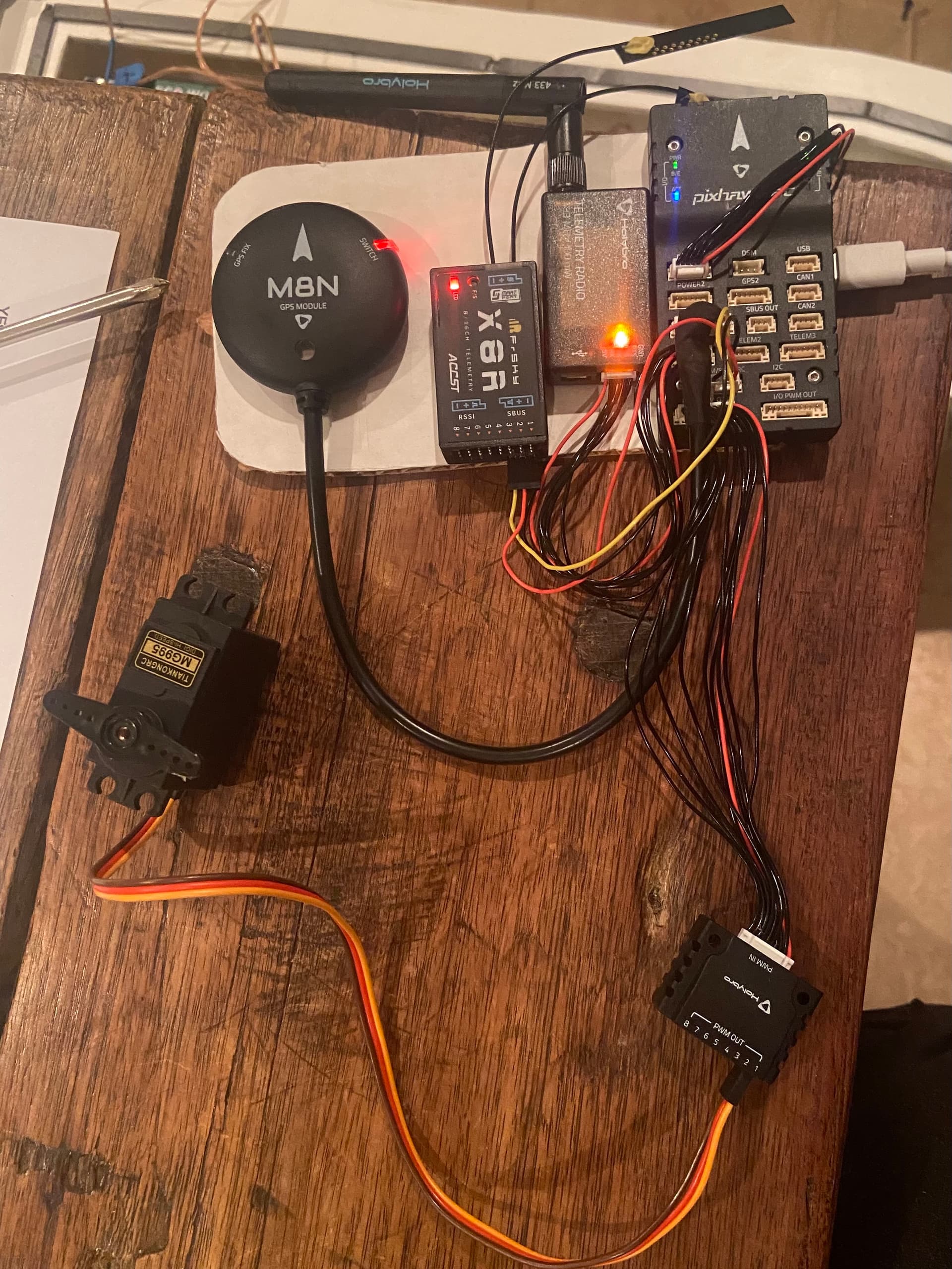
In the pic you have not powered the servo in any way… pixhawk controller servo connection pins do not have any power on the 5v pins you have to source it yourself from an escs bec or another bec or from somewhere that isn’t the flight controllers 5v supply
In the guide by Painless360, I’m watching for my setup, he does not use a BEC. However, I believe I have a much more fundamental problem as when the Pixhawk is armed and showing a servo output, I checked the signal and “+” pins with a voltmeter, and neither showed any sort of life. Is it possible that the board itself is flawed and has a broken connection to the PWM OUT port?
There is never 5v across + and Gnd pins of the io breakout (or pixhawk header for that matter) until you provide YOUR OWN POWER SOURCE.
the Gnd and 5v pins are indeed all tied together so just add a supply (a 4cell nimh or output from a bec or something) to the rail by plugging into an unused servo output.
an esc only needs just the signal wire as the supply battery ground is common to the pwm ground on the io header, but a servo needs a 5v supply
This is why I like the simplicity of the matek boards, no separate power module (it’s just the bottom deck of the FC, 6s input capacity (some pix power modules only good for 4s) and the servo headers are powered internally from a good bec with options of 5v, 6v or 7.2v at 8A cont, and 10A max. you just treat them like a reciever.
I’m having a similar problem. Ardupilot shows it’s getting the inputs but not getting anything out. I have the servo rail powered through a 5v output on the power distro and the esc’s powered from the 12v outputs. Nothing at all coming from the PWM outs.
What do you want to test, motors or servos?
If motors, how are you testing, through Mission Planner motor test or RC? If RC, did you arm it first?
If servos, what is your BRD_SAFETY_MASK parameter set to?
Without details what you want to do and what you did so far helping you is just guesswork.
I’m using the exact same procedure outlined above. X8R receiver plugged into the PPM/SBUS on the 6C testing for the servos plugged into the FMU PWM out (matches the photo previously posted above) except that I have the PWM rail hooked up to 5v on #8 slot (servo on 1 & 2 slots).
In Ardupilot, I see inputs in Radio Calibration and Servo Output (channel 1 is aileron and channel two is elevator) working, but I get nothing on from the servos. Tested by plugging servos directly to receiver and it works. Measured 5v across all the power pins on the PWM rail.
Setting the Servo output to Aileron and Elevator is a little unusual.
For motor outputs we’d normally expect to see one of the setups on this page so servo outputs should be “Ground Steering”, “Throttle”, “ThrottleLeft” or “ThrottleRight”.
In general it’s best to provide an onboard log because that gives us a lot more information to go on.
I should clarify, this is on a plane. I didn’t realize this was a ArduRover/Boat thread… I found my way here because this is an identical issue and identical hardware setup. Attaching log files, but I’ll go ahead and take this to a arduplane thread.