I have just bought a Pixhawk 4 and the full size power management board and I am knocking my head against the wall trying to make sure I wire it correctly before I power anything up. I think I am 95% there, but don’t want to take the white smoke out of something. (Every machine is a smoke machine if you operate it wrong enough)
I am trying to set up a rover first, but eventually will use this for a fixed wing plane. I am using Mission Planner for the first time along with a Dragon Link for control and telemetry. I think I have most everything connected correctly except for the servo and motor. I have followed the pixhawk connection guide here and have
‘Power 1’ on Pixhawk connected to ‘PWR1’ on the PMB
‘Telem1’ and ‘SBUS RC’ connected to dragon link receiver
Gps connected
I also have ‘FMU-PWM OUT’ on pixhawk connected to ‘FMU-PWM IN’ on the PMB, as I think that is correct as I just need 1 servo and 1 brushless motor through an ESC, but I am not sure if I need to be using the I/O PWM-IN instead? The airframes reference guide here says for a rover the specific outputs are
MAIN2: steering
MAIN4: throttle
Does that mean I will simply connect the servo and ESC to pins 2 and 4 on the FMU-PWM out? Or something else entirely?
Also related but maybe not the same question, I know my servo needs 6.6v somewhere. My ESC is supplying the 6.6V via BEC, but I also know the ‘FMU-PWM OUT’ does not provide power. Are all the power pins on the ‘FMU-PWM OUT’ rail interconnected together so that if I connect the servo and ESC there, my servo will be powered?
Here is a picture for reference to what I have now. Any help or advice is appreciated. I don’t want to burn something up the first time I turn it on.
Okay so I ended up trying it as in the picture. I have the FMU PWM OUT of the pixhawk 4 connect to the FMU PWM IN on the power management board and then the steering servo connected to output 1 of the FMU PWM OUT side connectors and the esc control wire connected to output 3 which is also supplying 6.6v for the BEC circuit, so the steering servo is getting that voltage. (I tested it with a multimeter).
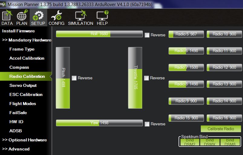
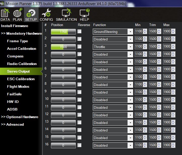
All that to say is I cannot get the rover to respond. I attached two pictures, one of the Radio Calibration screen and another of the Servo output screen. When I move the throttle and roll sticks on my transmitter, I can see the Throttle and Roll on the radio calibration screen move accordingly. (You can tell both throttle and roll are not at 1500 on the screen as I am actively moving them). On the servo output screen I can also move the stick left and right and I see the #1 ground steering position move accordingly. Unfortunately when I move the throttle I see no movement. Additionally, when I do the motor test according to the guide on ardupilot here, I get nothing. Not even the steering servo movement. What am I doing wrong? I have followed the other directions on ardupilot, but I am not sure what other way to hook things up as I thought I did everything per the guides. Any help?
Well, I ended up finding the solution to my problem, so here it is if any other noobs run into this issue in the future. First off there were actually several issues and all were user error. In addition I figured out the correct way to wire it for my configuration.
First things first. I run things mode 2 so had Channel 1 out of my receiver as the steering and channel 3 as throttle. Not exactly sure what the airframe reference guide means by saying Main2 and Main4 for steering and throttle, but using ArduRover 4.1 software it didn’t matter as I didn’t have it set up with the native pixhawk software. So at some point I knew I needed to use channel 1 and 3 FMU-PWM OUT on the Power Management Board as that what was set up in Mission Planner. The problem was they still weren’t working.
The next thing I realized along the way was the reason I could not get the throttle to move on the servo output screen but was moving on radio cal screen. It was that the throttle position slider on the screen will only move with the rover armed. I was trying to move it while the rover was disarmed. I had thought that I would at least be able to see it move like the steering would, but it doesn’t. (In hindsight it makes sense that way as only throttle gets armed and disarmed.) The only reason I wasn’t seeing the steering actually move on the car along with the display on the servo output screen was that I still had the vehicle wired wrong. For other noobs like me who don’t know how things work, in default Ardurover 4.1 you can move steering with the system disarmed. Not throttle.
Lastly was my wiring issue. I still don’t understand the power management board fully or the pixhawk 4 fully. I dont understand why there is a 10 wire connector ‘I/O PWN OUT’ and another 10 pin ‘FMU-PWM OUT’ on the Pixhawk 4. I am not sure what either of them technically does, or how to use one versus the other. But since there also was a ‘I/O PWM IN’ and a ‘FMU-PWM IN’ on the power management board I figured it made sense to connect the similar names together. I knew I probably should be using the FMU-PWM OUT pins on the Board to connect my servo and esc connectors to, so I first hooked up those. Didnt work. I thought maybe I needed both sets of 10 pin wires connected, so I put them all together… still didnt work. Only after struggling and thinking I had something wrong in Mission Planner for days did I end up just randomly switching and connecting ‘I/O PWN OUT’ of the Pixhawk 4 to ‘FMU-PWM IN’ on the power management board… And then it all worked!
Anyways, hopefully that makes sense to everyone else and in the future this can help some other poor soul from going crazy. All I know now is I am one step closer to the first drive. Fingers crossed.
I am having similar issues with my setup. Like you I have built a Rover platform to learn and experiment with PX4 and Mission Planer before applying that knowledge to other platforms. My Rover is a skid steer configuration.
I have the HolyBro Pixhawk 4 and supplied Power Management Board but I use a Sabertooth 2x12 for the ESC, HolyBro telemetry and GPS. My RC unit is the FlySky FS-i6X with FS-iA6B receiver.
I started out just getting the skid steer to work from the RC side. Once I had that setup I then plugged the Pixhawk in with the other parts. I Use the I/O PWM OUT from Pixhawk to I/O PWM IN on the PMB - I’m not using any servos at this stage, the receiver uses Ch1/PPM out pins to PPM RC socket on the Pixhawk. I’m using the FMU-PWM-Out pins to send signal for motor control to the ESC S1 and S2.
So that’s my physical wiring setup.
In Mission Planner I get the same results as you and no motor movement.
Would you mind helping me trouble shoot my setup please, I’m just going around in circles trying to get this sorted. Basically I just need someone with a different set of eyes and perspective that is doing the same thing as me.
Hello,
The quick answer is “Board is not Pixhawk4 but CUAVv5”. Use this to load the firmware in the board via “Install firmware” in Mission planner.
Info above is not available in no other forum, or documentation of the board. Found-it by mistake, when trying to disable GPS and found that the parameter “BRD_TYPE”, default at 0 (autodetect) will set itself to 24 (CUAVv5/FMUv5).
Nice controller and power board, but with incomplete specifications.