Anyone know what the Power Module settings on Arducopter should be for the power module that comes with the Pixhawk 2.1? I can see the voltage changing but don’t see any current information as of now.
1 Like
Bump, no one has any comments to help?
Any help would be really appreciated

Yup those are the ones. But looks like the parameters you are using are the same which means it should work for me too. Did your Pixhawk 2.1 power module’s current sensor work out of the box or did you have to do any thing?
If its working fine for you without any issue, it might be a power module with a faulty current sensor. Anyone else have this problem too?
I ran the old power module with the Pixhawk 2.1 and it worked without any issues. I tested the wires connecting the power module to the Pixhawk 2.1 and found them to be correct to have continuity.
A test on the new power module revealed that the voltage sensor sends the correct signal voltages based on the battery voltages but the current draw signal voltages are much much lower that the old power module. Could be a problem with the new module itself.
The current sensor in the new module is different than the old 3DR module(120A max in the new on versus an ~80A max on the old one).
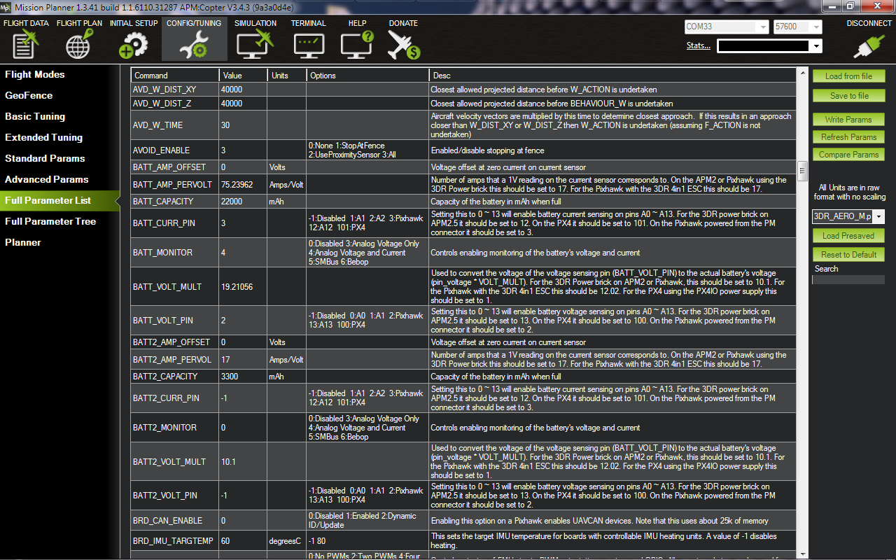
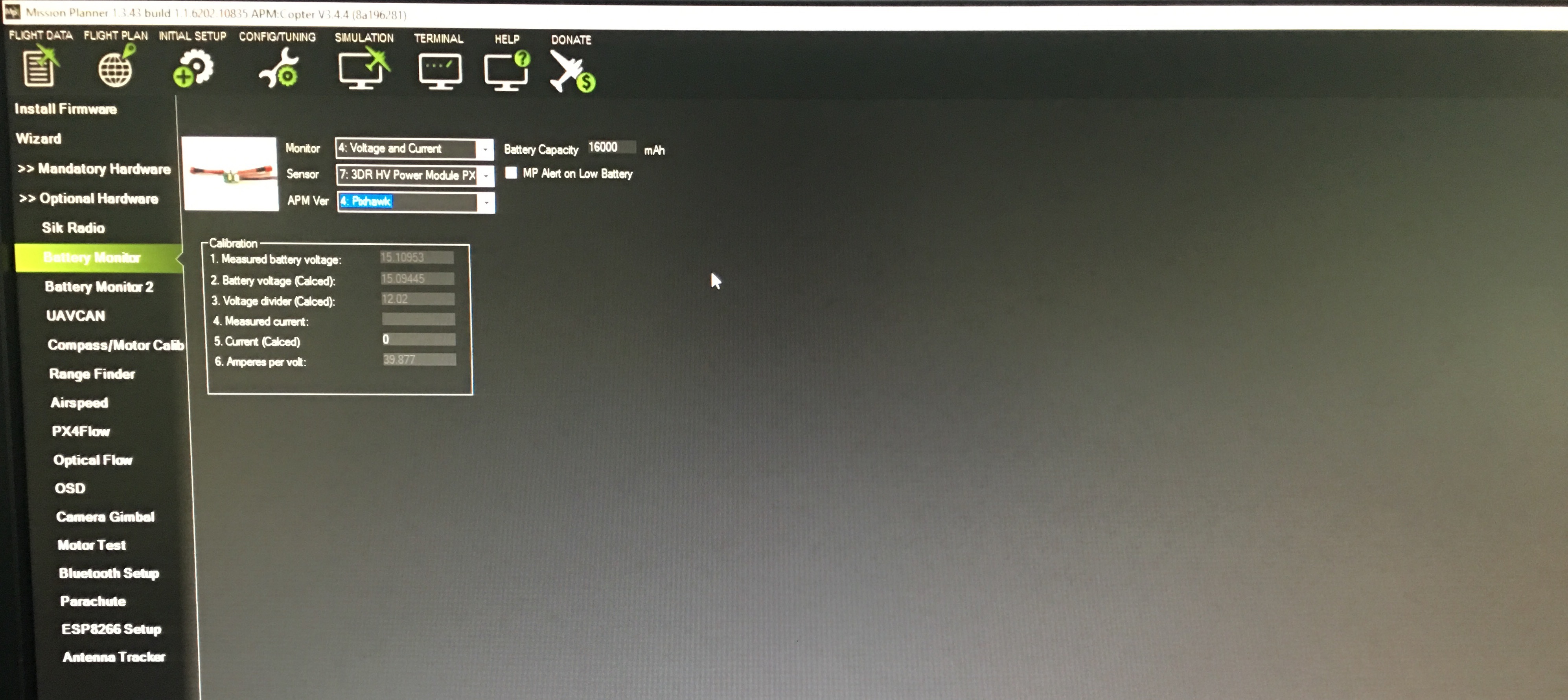
Look for HV power module in the list of power modules in Mission planner.
Isn’t the new power module rated to 30Amps and 8S?
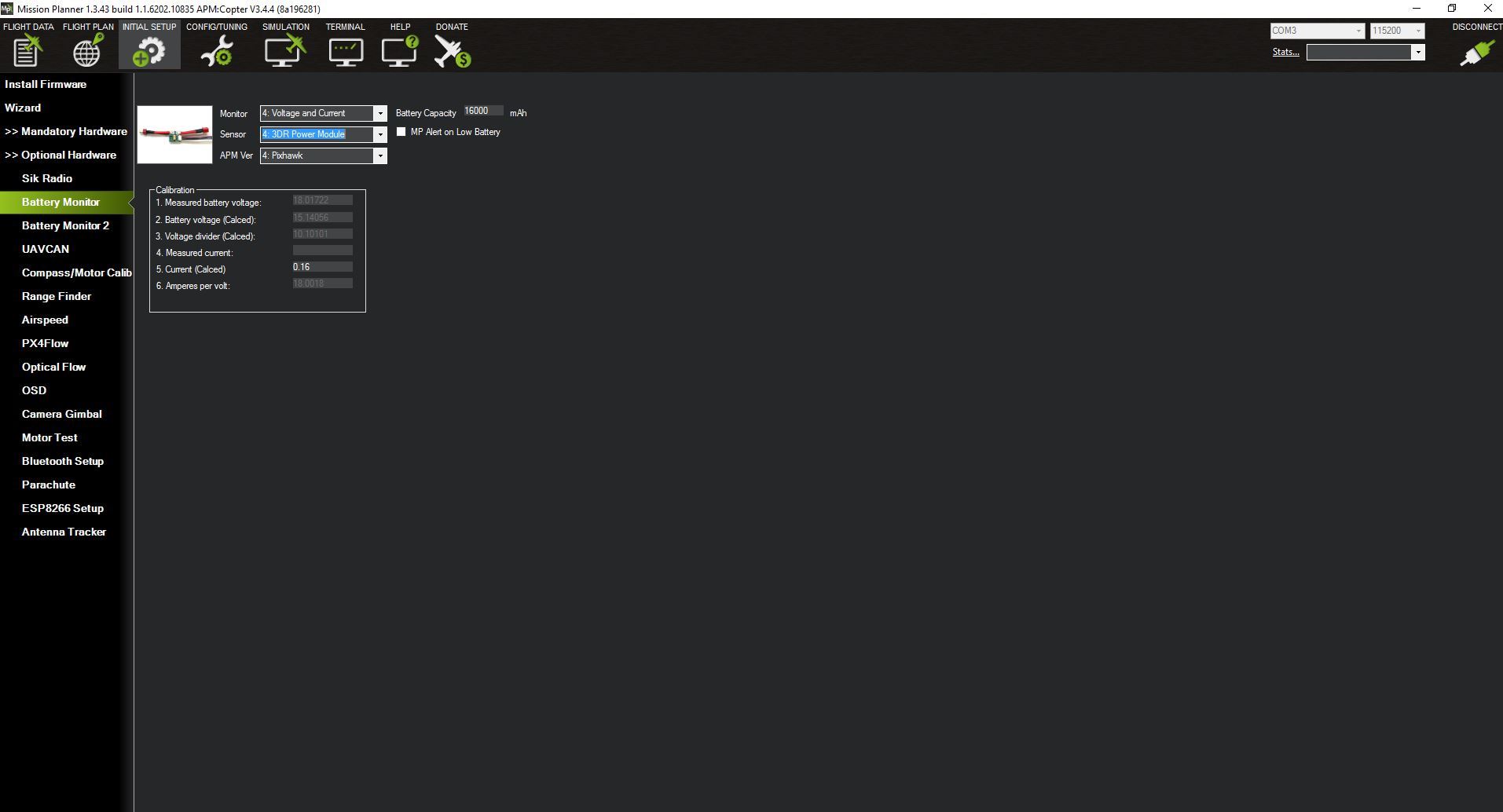
I have tried the “3DR HV Power Module PX4” as well as the normal 3DR power module option on Mission Planner but that doesn’t help.
80A (old PM) and 120A (new PM) are where the sensors clip the ADC in the Pixhawk. Ratings in the thermal domain are a lot lower.
Can you show me a screencap of the old PM’s amps per volt setting? (I don’t have mission planner installed on this computer).
The params all look right to me.
How much current are you pulling when you test?
2-20 amps are the currents we ran the tests with.
Any fix yet? I’m having the same issue. V works fine, A doesn’t show.
Maybe there is something you missed…
Sent back mine to get a replacement. Lets see what happens.
Ok, good. Could you post an update when you hear back?
vkt62 noreply@discuss.ardupilot.org schrieb am Mo., 6. Feb. 2017 um
14:23 Uhr:
Sure. I will post one once I get it.
Did anyone get an answer to this problem. I’m experiencing the same.
Please try the power module configuration in the beta version of mission planner.
Bump.
Someone found a solution?
What I saw is that at zero Amp the voltage on the current pin is -0.02. At around 5A the voltage is 0.06V. It’s weird that a sensor with 30A changes 0.08V for 5A.
I tried to install the latest Misison Planner Beta and it always shows 130A. I think the problem is Mission Planner side, where the battery monitor tab was always working very bad.