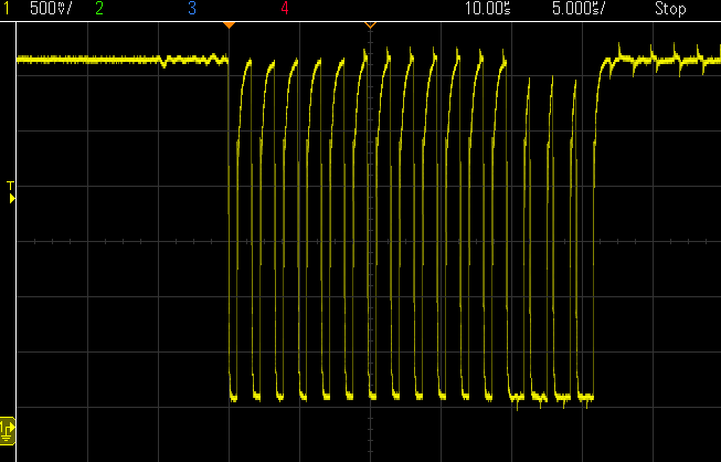
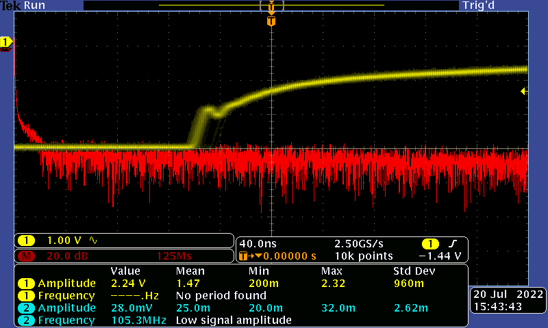
I ran a quick test of your params, and took some traces to demonstrate what you’re seeing. The following is a DShot pulse train with similar wire lengths to what you’re running, measured at the ESC. It will occasionally accept this as a valid signal, but I wouldn’t fly with it:
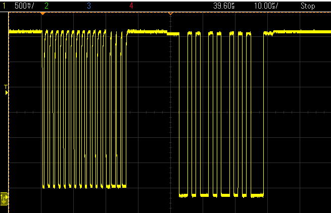
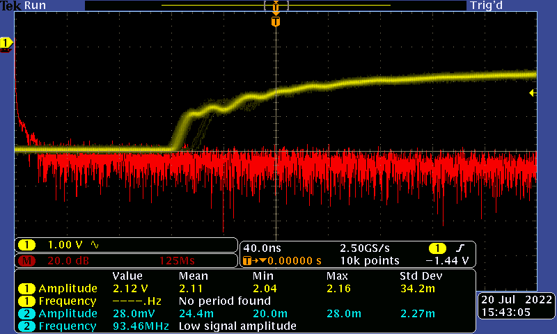
Shortening the leads (to around 10 cm) and running the same measurement results in the following pulses, which are accepted:
You may see better performance on your end if you run the wires in a twisted pair configuration (if you haven’t already).
I’m not sure what the implication is, just following the Ardupilot documentation. One of the devs might be better suited to jump in here.
Diagnostics are for our debugging units during this Beta phase. It won’t return any status data.
Thanks, Vanja. You were spot on about the signal leads picking up noise. Thank you for the scope tests as well. When I shortened the length to about 4-6 inches (10 - 15 cm) all six ESCs were blinking normally. 50 cm of flat signal leads showed normally blinking LEDs as well. I think it will “accept” up to 60 cm of signal wire length flat but I don’t know what the quality of the signal will be. This begs a few questions:
How does one build this with anything that is not a small racing quad? My drone isn’t that big – 960 mm drivetrain. I can’t get the ESCs too close to the flight controller because they need to be cooled by the props + motors. Besides, there will then be long wires going to the motors which can also pick up noise?
Let’s say I get it to “accept” with 60 cm of length but there is noise pickup mid-flight. Will that be catastrophic?
I asked about that here. There is also someone who seemingly got it to work on a hex here.
Good to hear. Make sure they’re a twisted ground pair to keep the inductance as low as possible. Both good questions:
Lower loop rates and baud rates are usually recommended for anything outside racing. You can utilise additional inline hardware (such as Schmitt trigger buffers, etc) to supplement the drive output limitations of the Cube hardware. This one gets complex with bi-directional signalling such as required with RPM filtering. From an ESC point of view, we prefer shorter inputs when compared to outputs. This leaves your bus wires shorter too, and requires less capacitance. You are correct though, 3-phase motor wires generate a fair amount of EMC depending on power outputs. There is also the balance of cooling to consider.
You will need to lose 500ms worth of packets for the ESC to shut down the drive (lots of consecutive when running DShot). We do have a reporting system for signal quality since power up (see here). The criteria for ‘bad’ signal is the detection of a greater number of failed pulse trains vs passed trains at any given time. Keep in mind DShot throttle commands are checksum protected, so it is unlikely noise will make it from the signal line to motor drive output.
Great answer, Vanja. Thanks again. I suppose I’ll have to test it out on a scope like you did. Can you help me interpret your scope plots? What indicates a “bad” signal line exactly? The amplitude is < 3.3V in the first plot. What else am I looking for?
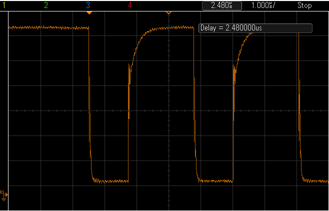
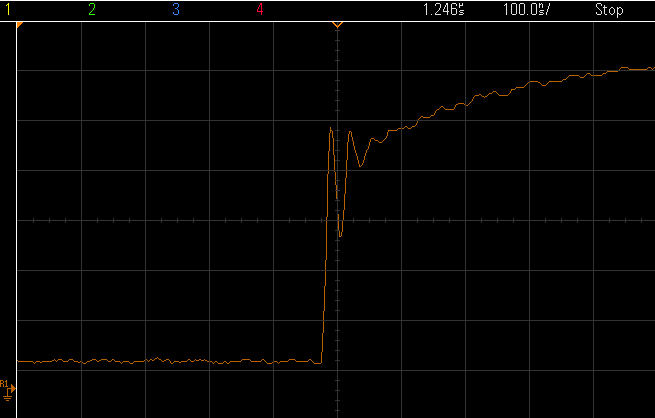
While having a 3.3 V signal is important, in this case, it’s the pulses themselves that are the source of the issue. A closer look at the first capture from my reply above can be found below, where you can see ringing occurring during rising/falling edges.
DShot is very timing critical, and such ringing will trigger false readings, which the ESC is treating as noisy/failing packets. What we want to see in the above are well defined, ‘square’ pulses within the pulse train.
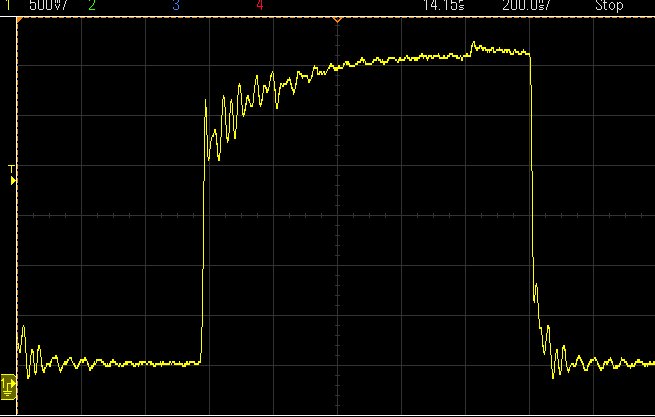
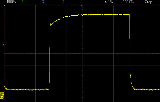
Here is what I have with some scope tests of my own. I tested with a 150 cm signal line and a 15 cm long signal line to an oscilloscope. In both cases I see very little difference in noise but it is enough to make the ESC stop working. Some plots attached below.
All wires were flat and untwisted. I am just trying to characterize the ESC behavior wrt wire length. Did I do this right? Do you have a spec on how much noise the ESC can tolerate? I am concerned that even with twisting wires, adding ferrite beads, or metal shielding there could be some noise pickup mid-flight which would cause them to shut down. What do you think?
How have you wired the above? The voltage is quite low (remembering the cube outputs >3 V).
The units are most sensitive to noise during the initial phase of signal acquisition, as all the filtering is turned down to allow detection of high speed pulse trains (DSHOT1200, etc).
Once the signal is acquired, the appropriate filtering is applied for that rate. A cause for concern would be once the signal is acquired, the detection/rejection of a vast number of incoming packets is still occurring (this tone is played). Remember that for the units to shut down, there needs to be 500ms of no signal at all.
I was seeing 3-3.3V for the most part. The screenshots above show the amplitude for the window that it is currently set at (I have zoomed in to see the ripples).
The noise profile seems pink in nature but when I look at it in Fourier space I can barely resolve the difference between the 150 cm and 15 cm case. What type of filters do they have? High pass?
Hmph. Wonder why I am seeing less noise on the scope. What baud rate have you set it at?
I think I am just going to twist the cables, add some metal shielding and some ferrite beads for good measure. This is probably overkill but my drone can take the additional weight and I would rather err on the side of caution.
It’s worth noting that for racing quads they often use 4-in-1 ESCs in a stack with the FC. It’s better electrically to have long wires from the ESC to the motor than long wires from the battery (and FC) to the ESC.
I’ve had some 10-15 gentle hover tests with the drone and new APD ESCs for tuning my PIDs. However, off late I am noticing this:
This happens when I am throttling up for an Alt Hold test. Sometimes this happens and I just throttle up and it flies okay but off late it is happening a lot and I am concerned it is indicative of a more serious underlying problem. I checked the motors with my old PWM ESCs on the bench and they spun just fine so it’s not the motors. I am going to try spinning them up with the APD ESCs but I was wondering if you have seen something like this before.
I also tried changing from Dshot600 to Dshot150 but that didn’t fix this issue.
Definitely a cause for concern. If you move that ESC around, does the issue remain with the channel (indicating a wiring/motor issue), or follow the ESC (indicating an ESC hardware issue)?
Does increasing MOT_SPIN_ARM,0.07 a bit change the behaviour?
In the video it actually looks like a connection problem between motor and ESC.
Have you tried the ordinary Cube firmware instead of BiDir-DShot ? I could be wrong but I thought the bi-dir DSHOT was only tested with quads, but it might be OK for a hex or octo, unsure…
You would need to have the telem wires joined and connected to a RX pin of a serial port, and a couple of suitable params for that to work.
I would DEFINITELY be setting the BATT_FS_ params.
@Vanja_APD: I think it was a connection issue. When I took it all apart, I found the servo cables slightly loose. Replaced the connectors and put them back in and the motor stutter is gone. Not sure if that can cause the motor direction to change but I will do some more tests and confirm.
@xfacta: I am getting 6 notches at fundamental and then for two more harmonics. That is a total of 6 * 3 * 3 = 54 notches, which is the current max supported. It’s strange because I was told only 4 motor inputs would work but there you go. ESC telemetry is working as well.
I know you mentioned the BATT_FS_ stuff to me before. I haven’t changed it yet because I keep getting low voltage warnings during my manual tune hover tests and I am not sure what the behavior will be in that case. Does it do a RTL or Land during Alt Hold? What if it happens during Autotune?
Have you got the latest .bin log to see what’s going on with the battery?
I find that using the correct params as calculated by the Initial Parameters and getting early fail safes means you have
the voltage calibration wrong (or there’s more resistance somewhere than you expect)
the battery is worse than you expect
Disabling the failsafes only leads to bad outcomes or the battery keeps getting worse and worse.
It will do RTL if you have that set as the action, but if it is within the (inverted) “Cone Slope” it wont rise to RTL altitude before returning to home, essentially just repositioning and landing.
RTL_CONE_SLOPE,3 = 3 vertical distance unit for every 1 horizontal distance unit = a steep inverted cone, easy to be outside this cone meaning climb to full RLT Alt !
RTL_CONE_SLOPE,1 = 1 vertical distance unit for every 1 horizontal distance unit = very shallow inverted cone, easy to be inside the cone but be aware of obstacles
I use:
BATT_FS_CRT_ACT,1
BATT_FS_LOW_ACT,2
RTL_ALT,4500
RTL_ALT_FINAL,0
RTL_CLIMB_MIN,200
RTL_CONE_SLOPE,2
Direction changes will occur if one of the phase cables is not connected correctly (ESC needs 3 phases to maintain control in the desired direction), or a phase is damaged. Given it’s intermittent, it would point to a connection issue (the nice part about power electronics is that it either works or doesn’t).
Thanks, Shawn. So far, I have seen little reason to doubt my battery. It is a new battery and I have just started using it. I think I get battery warnings if the starting voltage was medium or low and there is a sudden but transient voltage drop due to throttle. See ESC voltage plot here.
I have noted your concerns about it and will enable these settings when I move on to full Auto missions. I just don’t want any unexpected behavior when doing tuning flights.
P.S. Did hover test today. It worked fine, save for my current outstanding PID issue so this ESC problem seems to be resolved.