Hi,my question is that could you tell me if it’s necessary to change the software code inorder to enable uart 4 on Omnibus f4 pro V2 ( it has I believe UART 1, 3, 6) or you can also do it with just putting BRD_ALT_CONFIG to 3 and nothing else at all in mission planner, I needed a ground station telemetry but due to lack of uart port I can’t do it.
For example
Uart 1 - SBUS receiver
Uart 3 - Compass (as it is natively an I2C connection but can be converted to uart but I don’t want to as I need a compass)
Uart 6 - GPS
And if possible Uart 4 - telemetry (Sik telemetry probably)
BRD_ALT_CONFIG = 1; I2C disabled (USART3=SERIAL2), RSSI & PWM5 active as usual BRD_ALT_CONFIG = 2; I2C enabled, RSSI & PWM5 disabled (UART4=SERIAL4) BRD_ALT_CONFIG = 3; Both I2C and RSSI & PWM5 disabled and are used as UARTs
Note that UARTx to SERIALx map is here and is board specific.
What your missing is that ardupilot does not need the uart for sbus, it can use the ppm input for SBUS for that leaving uart 1 free as ardupilot has a much more sophisticated rc input that can auto detect protocals. Betaflight and inav cant do this and have to use a uart port.
PPM solder pad/resistor should be soldered and “S-BUS” resistor/solder pad removed Otherwise, UART1 or UART6 or RCIN will not work.
Thanks for responding,
Yes I have looked at that and I understood the basics from it but the thing is I saw another post on ardupilot forum where someone said that they edited the hwdef file to repurpose rssi to uart so as to get uart 4 available, but I don’t know how to edit the software code on mission planner. I am currently assuming the document that you shared as the correct idea to do so where you just need to change the parameters for BRD_ALT_COFIG to 2 rather than 3, now that you pointed its effects out but I just need confirmation as to whether I’d have to change software as well because from a logical point of view, it seems kind of wierd that you’d have a frontend option to change your pin functions but then also have to change the code to do so.
Hey thanks for responding,
That would have actually made my life really easy but on Omnibus f4 pro V2, atleast my board for that matter, the ppm/SBUS and uart 1 are all on the same pin so basically if you’re using that pin, let’s say for serial RX, you can’t use it for anything else. That is why I wanted to use the rssi pads, as I don’t use it anyway to get an extra uart, which as the document on Omnibus F4 suggests can be done by changing the parameters for BRD_ALT_CONFIG and using pwm 5 as rx.
There is a jumper that connects ppm to uart1 you just need to remove it. its the one right next to the RC input pins. I have around 6 of those boards I use them in just about everything.
That sounds useful, could you be just a bit more descriptive and explain how do you then change the rx input to some other channel and isolate uart 1 on mission planner ? And could you confirm which pads have to be disconnected inorder to do so, I’ve attached a diagram
You should follow up with @geofrancis about the soldering part, as he has done it before (note that there are guidance pictures in the webpage we linked).
But about the frontend pin assignment - it’s not too complicated, in a simplified way:
There’s a hardware definition file (hwdef) that contains all pin assignments, which is compiled into Ardupilot firmware.
It can also have conditional assignments, which are also reflected in the firmware. That’s all.
The STM32 chips can be configured in several ways, as some of the pins can be configured to be GPIO, UART, I2C, etc. (but not at the same time).
Yes that is exactly what I was going to get at aswell as far as the “more” advanced software changes are concerned, so I’m glad you brought it up and that exact procedure regarding hwdef.dat file was provided in the other forum discussion that I hinted towards aswell, they went so far as to even provide what lines of code to change and to what, but from the context of a ardupilot newbie, I did not get how they accessed the software part in the first place of mission planner and then to make changes to the ‘hwdef’ files. So I was hoping, since that is brought up, could you tell me what I need to do inorder to access those codes and how to successfully alter them? And I don’t want to take up a lot of your time so just a specific answer for my case of accessing the hwdef file would also work.
I don’t you need to access the hwdef.dat file.
But if you do, you’ll have to compile Ardupilot’s code yourself, following this guide (since editing the hwdef.dat is the same as porting to a new board). It’s not very easy if you’re not familiar for compilation and ubuntu environment.
That is outside of MisisonPlanner scope.
What you can, and should do:
Change the BRD_ALT_CONFIG parameter via MissionPlanner
Solder or un-solder the required parts
Since it’s not clear exactly which version of flight controller you’re using, it’s hard to say what you should solder (if at all needed).
Link an exact datasheet or product page, or upload high quality images of the controller.
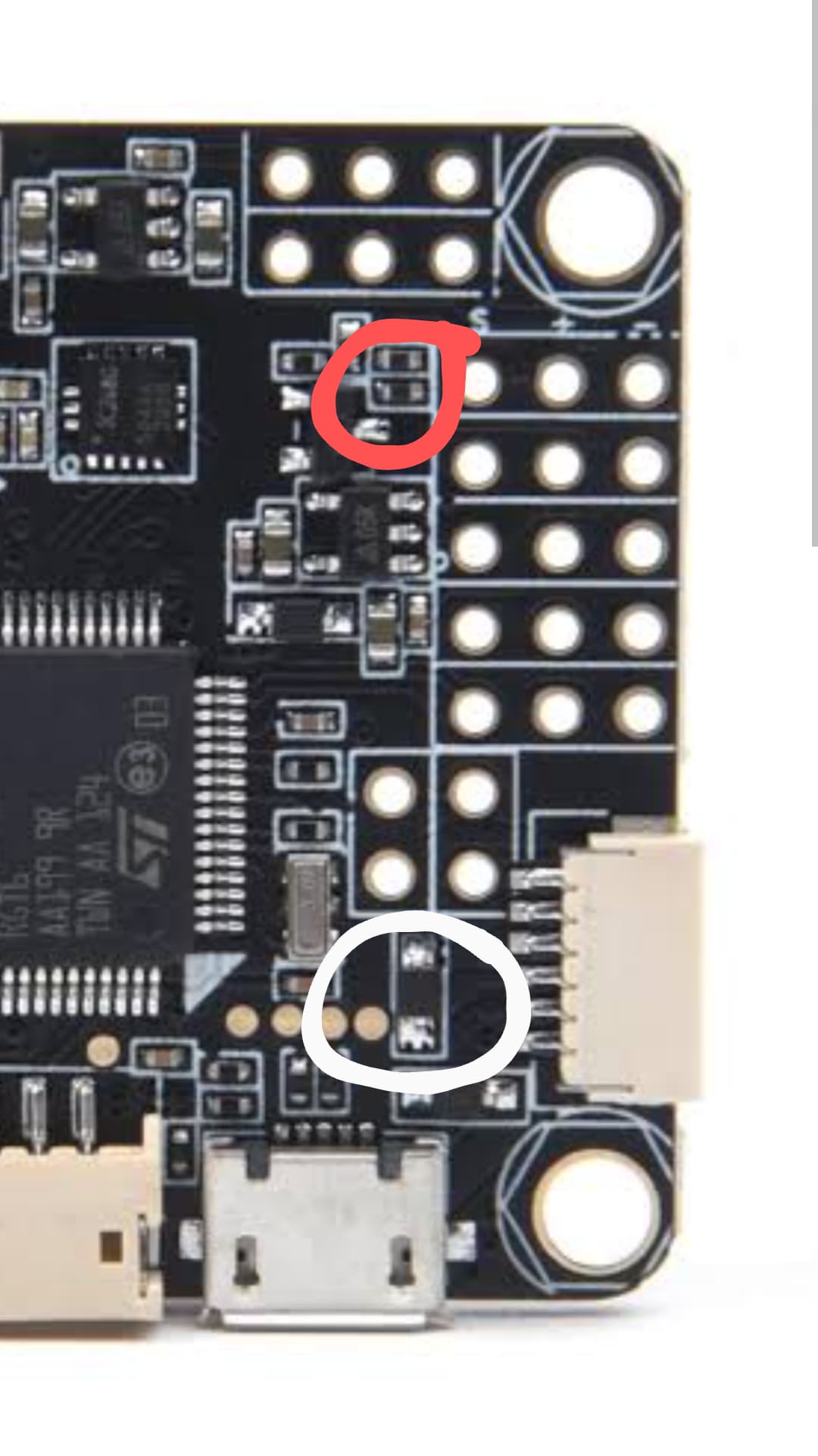
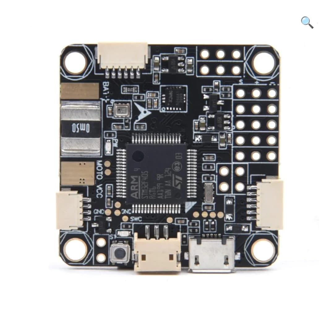
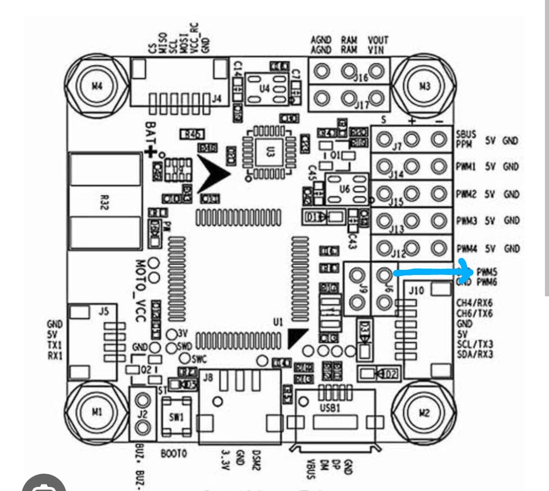
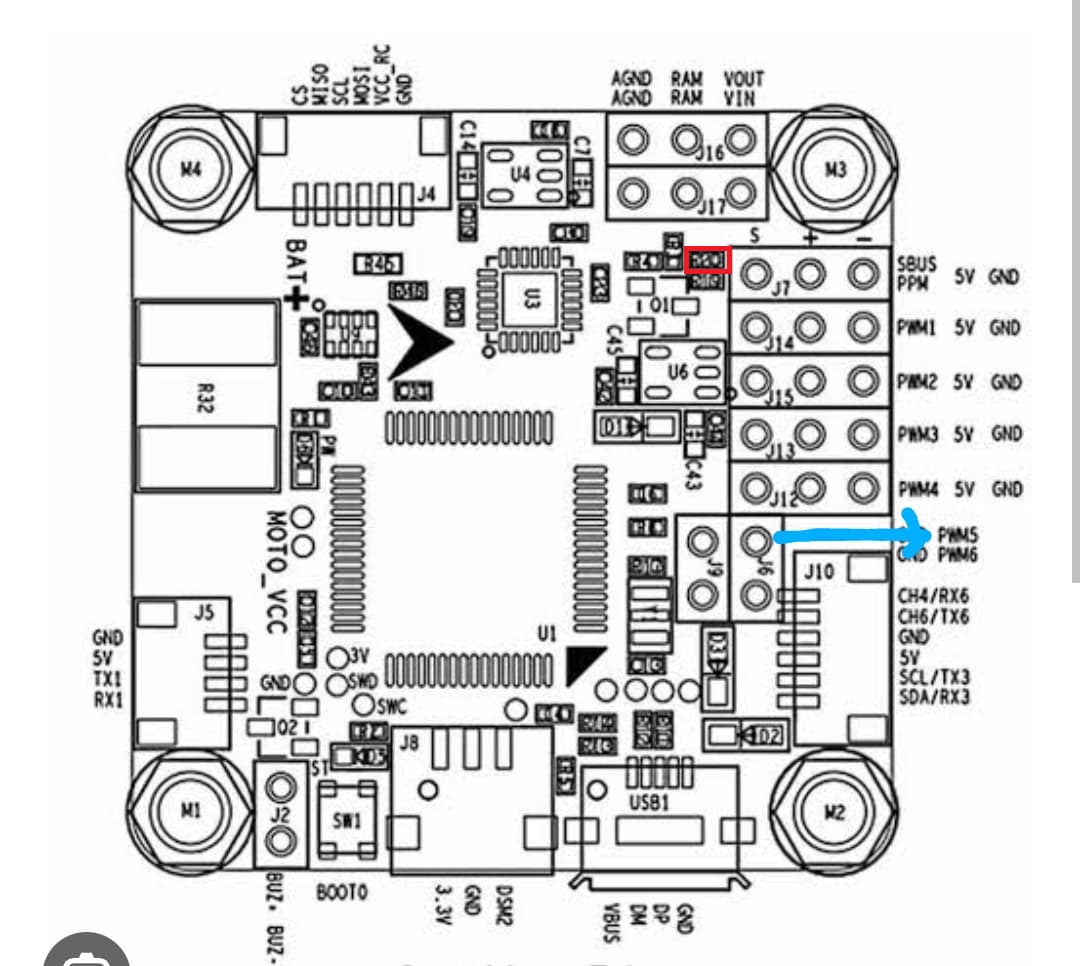
Well I am using exactly an Omnibus F4 pro v2 board but I believe relative positioning of some features on the boards varies as there are a lot of copies as well so this is the best image I can manage rn of the board as I’ve given it to one of my buddies who solders way better than me inorder to solder tx and rx to the rssi and pwm 5 pins respectively. See if you can figure something out and could you also confirm to me where exactly the pwm 5 pin is on the board (I’m completely new with this board and found no image that would give me a straight forward answer )
You’re going to have to provide an image of your board, the ones pictured are different than the one seen here.
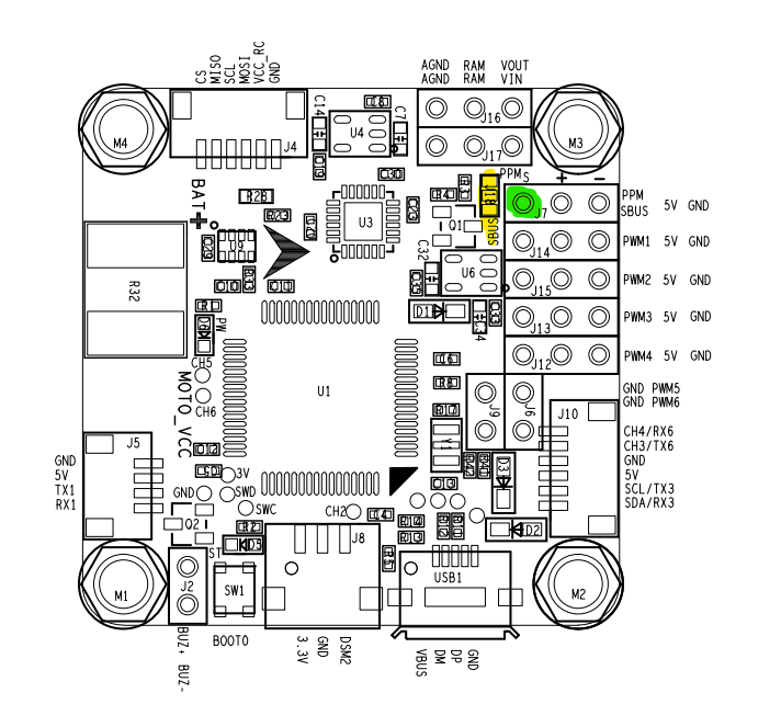
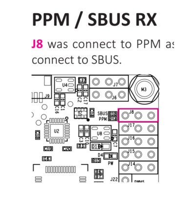
Originally the solder bridge needed here:
There are 3 pads very close to each other.
The center pad is connected to the J7 signal (highlighted green).
You need to connect the center pad to either PPM or the SBUS pads with a drop of solder.
I’m not sure how it translates to the board version you sent as a reference.
Have a look here and try to figure out yourself what to do (should be easy enough).
I think its this resistor that needs to be removed, from what I can find out your board is an earlier version, its confusing with so many clones as I am seeing sellers just mix and match version.
Well whenever I search it up on YT or Google I mostly get images of the same board that I have for Omnibus F4 v2, and I just saw the other board with 8 consecutive pwm pins (F3) the ones which you guys suggested, man I’m confused what is what now but thank you for your inputs and just to keep confusion out of bay, I’d assume it’s F4 since it has worked decently with that assumption till now but I think that’s more than enough info for ppm connection but my primary question is “how do I configure the parameters in arduplane so that I still have uart 1 available at the end of the day and ppm in some other pins other than the pins above PWM1 labelled SBUS/ppm (j7) ?”
I ask this because my SBUS/ppm(j7) pin and rx1 pin are interconnected so they are basically one hence I need SBUS/ppm( j7) pins isolated inorder for uart 1 to work, hence I figured if possible then move the ppm somewhere else (not a uart pin tho)
you are supposed to remove one of the resistors to separate ppm and uart, you just have an early version of the board that used actual resistors instead of the solder bridge later versions have that made the process easier.
Yes, I got that part pretty clear now but are you saying that once I remove the resistor, the
J7 pin would act purely as ppm pin and nothing else
my tx1, rx1 would act as uart 1
most importantly, there would be no interconnection between the two, meaning both would be entirely separate entities unlike how they behave right now.
Yes j7 will only act as ppm pin as we are removing the link to the uart port by removing the resistor, both will be fully independent and it will operate like the instructions here