Omni motor sailing boat

Voltage booster for the thrusters arrived along with the new connectors and boxes.
one box is for everything power and motor related, so escs, pdb,power module, i2c power sensor, battery balancer and mppt charge controller. the other box is for the pixhawk and its sensor inputs like the sonar control boards, the leak detector control board, there is also a third box with a esp32 that holds the rest of the sensors.


I2c INA226 power monitor is working and will get used for monitoring the solar panel output.

Phone mount complete, I wanted something I could fold for transport and go pro brackets are ideal. There is an alloy mount screwed to the deck. The waterproof phone case is attached to the bracket with a 3d printed gopro adapter glued to it. This way I can get a clear view of the boat and its high enough to alway be clear of the water.

2 Likes

Nice project and good progress.

Thank you for sharing.

2 Likes

I picked up a couple of these cameras from a clearance shop for just £8 each, the specs aren’t anything special, its just a pan and tilt wifi camera but these cameras come with an app I have used before the reason I remember this app is that works across the internet without opening ports. This means there is a server somewhere that is assisting the connection. I am not going to comment on the security of these cameras but let’s say I wouldn’t install one in my bedroom. That being said it makes them ideal for use from remote sites using mobile connections that don’t have a public ip or port routing capabilities. Like a phone on a boat.

The other issue is waterproofing the camera so I have ordered a display bell jar to mount it in.


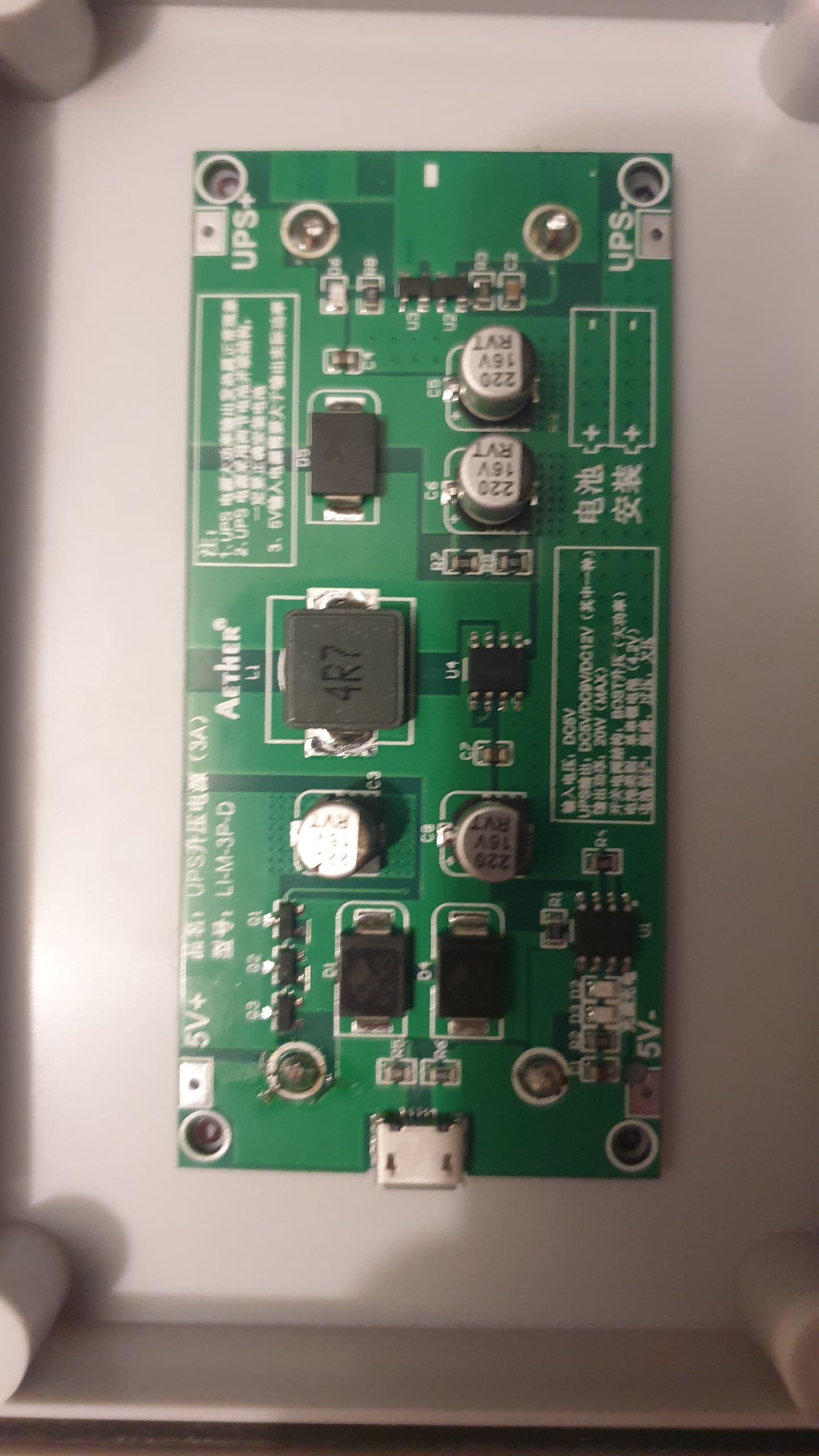
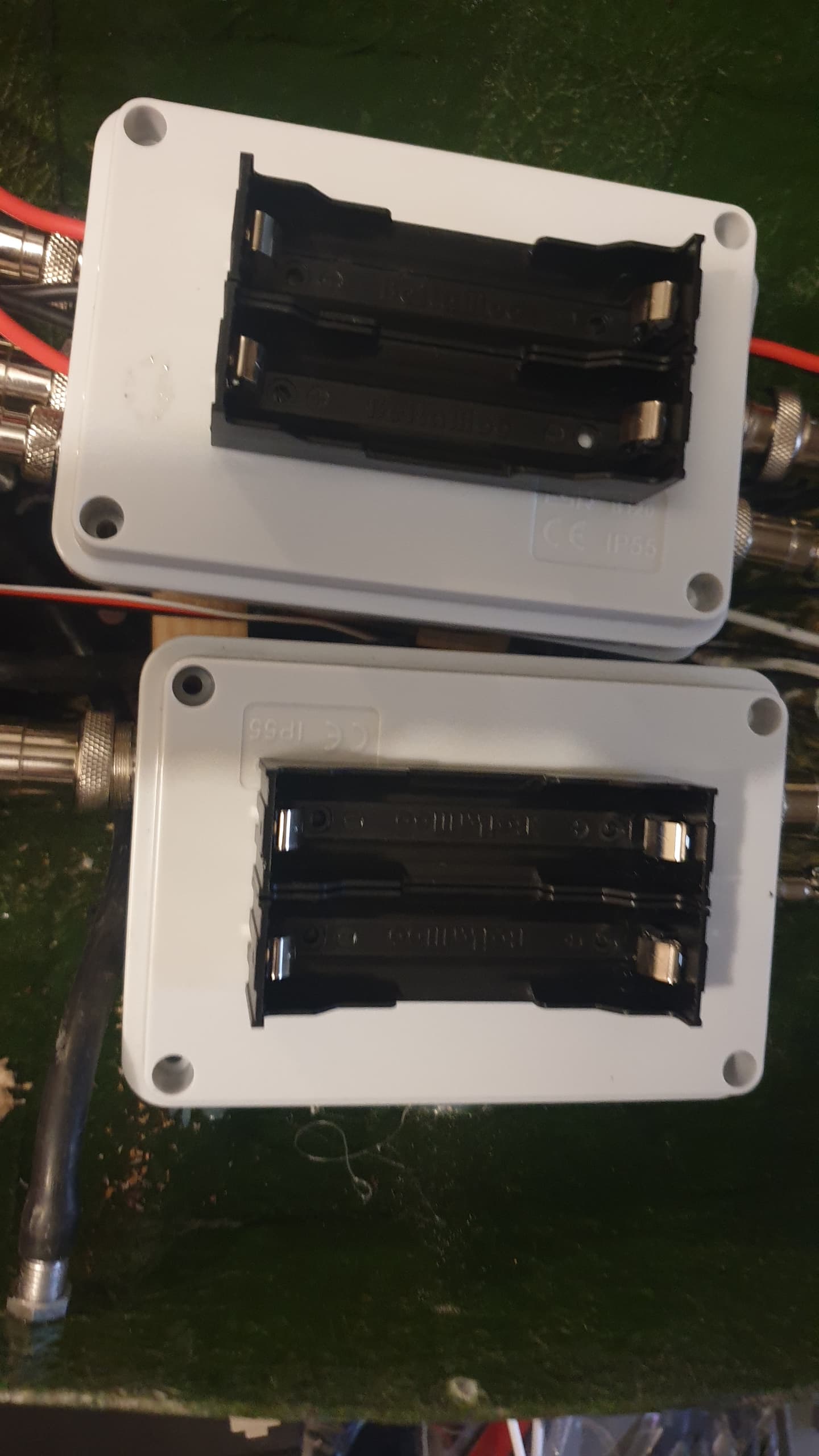
The 18650 5v ups power supplied are fitted but still to be wired up, the left one will power the servos and pixhawk via the servo rail then the right one will power the pixhawk via the USB rail and the phone in the event of the main battery going offline.


I’m really enjoying watching this build. This boat is going to have everything!

Looking at the pics of the pixhawk- is it aligned with the centerline and firmly mounted? I’ve had troubles just stuffing it in a box because the motion of the gyros/accels won’t agree with the compass and the IMU gets unhappy. Sorry if I’m misreading the image, and looking forward to seeing it sail!

1 Like

@meholden I will remove it and calibrate the pixhawk and the compass on a separate jig then reinstall it, that way I don’t have to try and move the boat around. The pixhawk just sitting in the box for now until the wiring is finished then it will get properly secured. im waiting for the uhf rc system and wind sensors before its going in the water.

Wind sensor has arrived but it doesn’t come with electronics its just the plastics, I have a angle sensor and hall sensor to get installed.

I have 3d printed an adapter so I can mount it to a gopro arm, it needs some tweaks so il probably do another one soon.

It will be getting mounted on the bow im just using the phone mount for fit testing till the new adapter arrives.


1 Like

Openlrsng modules have arrived. I used to use this years ago for rc and mavlink telemetry, the openlrs hardware has a number of flaws but its cheap and it works as long as you don’t mistreat it. its mavlink1 but thats fine as its only for a backup, 4g will be the primary.

I worked out how to mavlink 9xr pro radios with openlrsng many moons ago and my friend wrote it up.

the main issue with openlrs modules is to get it to work the atmega328 is ran at 3.3v @ 16mhz, this is well under spec and causes the eprom to corrupt if you brown out the voltage or power cycle it too fast so you loose all your settings. The way I got around that was it gets its own backup battery with a soft power switch so it cant get cycled or loose power.

out of the box the orange modules run around 400mw, due to the design running everything on 3.3v including the PA on the RFM23BP radio module, this can be increased to around 800mw by modifying the pcb and adding a 5v supply for the PA. I once build a version with selectable power output, it worked by adding a switch so I could select between 3.3v and 5v to the PA. When I first tried to hotswitch it the module would always crash, but adding a large capacitor it could switch power sources without interrupting the module.

The other reason for using this system is that it can do extreme range by running the radio at very low rates, at 4800 baud I could get 16 channel rc @ 9hz and full mavlink telemetry at around 500 bytes/s, it doesn’t sound like much but I could still load parameters and upload waypoints without issue. the 100mw version of this is used in cube sats.

Its good fit but I suspect I will have to disable the ir leds so the camera doesn’t get blinded by the reflection.

Hi, what ESC’s exactly are you using? I too am keen to get BLHeli ones and get the telemetry from them working.
Thanks

1 Like

Hey @geofrancis,
I see you are using some I2C INA current sensors to get your solar currents. I’m pulling that info directly from my MPPT chargers. They are Victron BlueSolar MPPT 75/10 Chargers, and you can connect to them and extract a data feed. It’s a serial connection (UART) to my Adafruit Feather M4 CAN which is running the code to parse out the various parameters I want like Solar panel voltage, current, MPPT charger state, heaps and heaps of data. The accuracy of the readings is definetly good enough too. I’m happy to share what I’ve done if anybody is interested.

1 Like

I’ve put some work into getting the data up almost in realtime up to a free instance of Grafana Cloud and have created a few dashboards which have proved super helpful in spotting issues.
It’s nighttime at the moment, so the panels are not generating :slight_smile:
.


1 Like

cool, I am sending my sensors to a domotics home automation controller archiving and monitoring.

I have just started fitting my dual transducer sonar. Testing has shown it works in as little as 15cm of water.

the ina power modules are surprisingly useful for low power monitoring, my solar system will never make more than 3A so they are ideal for my uses,Its also easy to change the i2c address on them so you can run a lot for monitoring individual batteries, I will probably be adding another 2 or 3 for monitoring the 5v backup batteries .

The main battery is going to be monitored by a Smart BMS, it will have UART and get interfaced directly with ardupilot eventually but il just bluetooth to it from the phone to monitor cells and configure it for now.

to get telemetry, you need a blheli32 ESC with current sensing and a telemetry pad. not all blheli32 escs can do it.

1 Like

Hey great project !
Cheers.

1 Like

My AIS receiver arrived. Tested it with USB bit not the pixhawk yet.

Angle sensor for my wind sensor arrived too, it was a little stiff do I immersed it in a vacume chamber with some wd40 to degrease it so it runs smoother.

My multi target avoidance radar arrived


Finished modifying my AIS receiver, I was hoping to figure out what rf modules they are using, but the chips are all ground down.

Cpu is a STM32f103

I modified it to simply the wiring. I don’t need rs232 or rs432 so I soldered a wire to the input of those chips to get a ttl level signal, I also wired a 5v feed in directly bypassing the onboard regulator, it uses less than a watt so its not an issue.