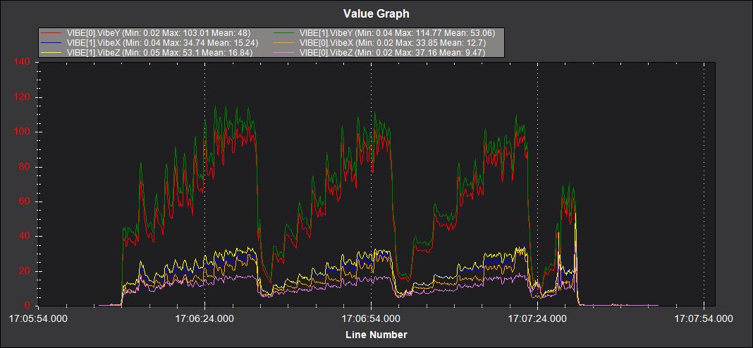
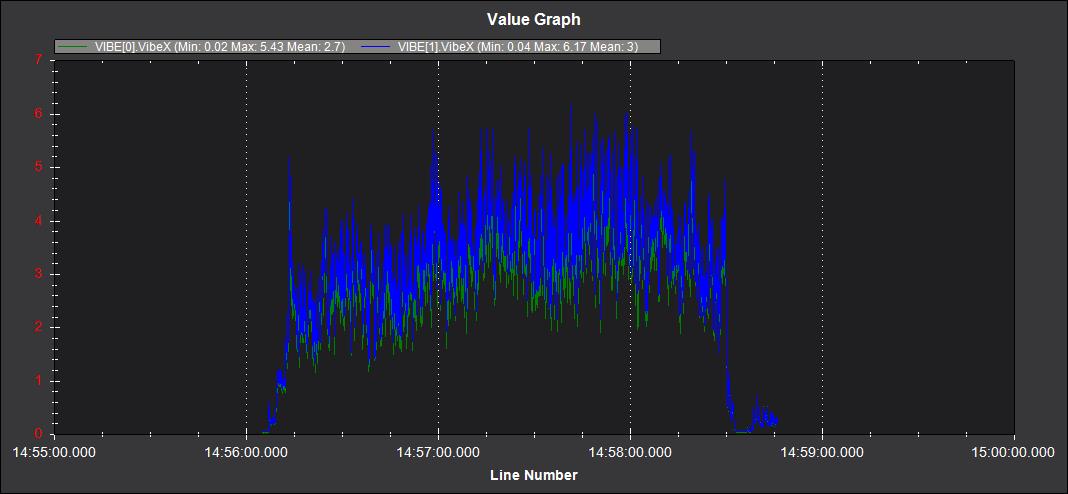
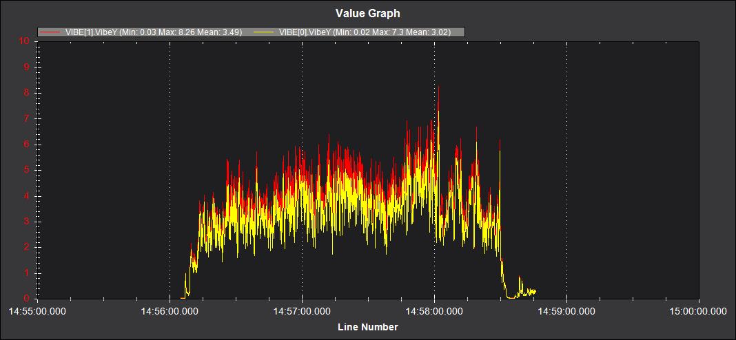
I have a baffling bit of vibration on a 670mm DYI quadcopter.
As you can see in the attached image, it appears to be rhythmic, builds up, sorts itself out, only to do it again. I thought it was only the Y axis until I graphed the others, but X & Z exhibit the same only lower, so assume for the moment the Y vibration is exciting those axises.
From multiple tests, it appears the rhythm is 25-30sec.
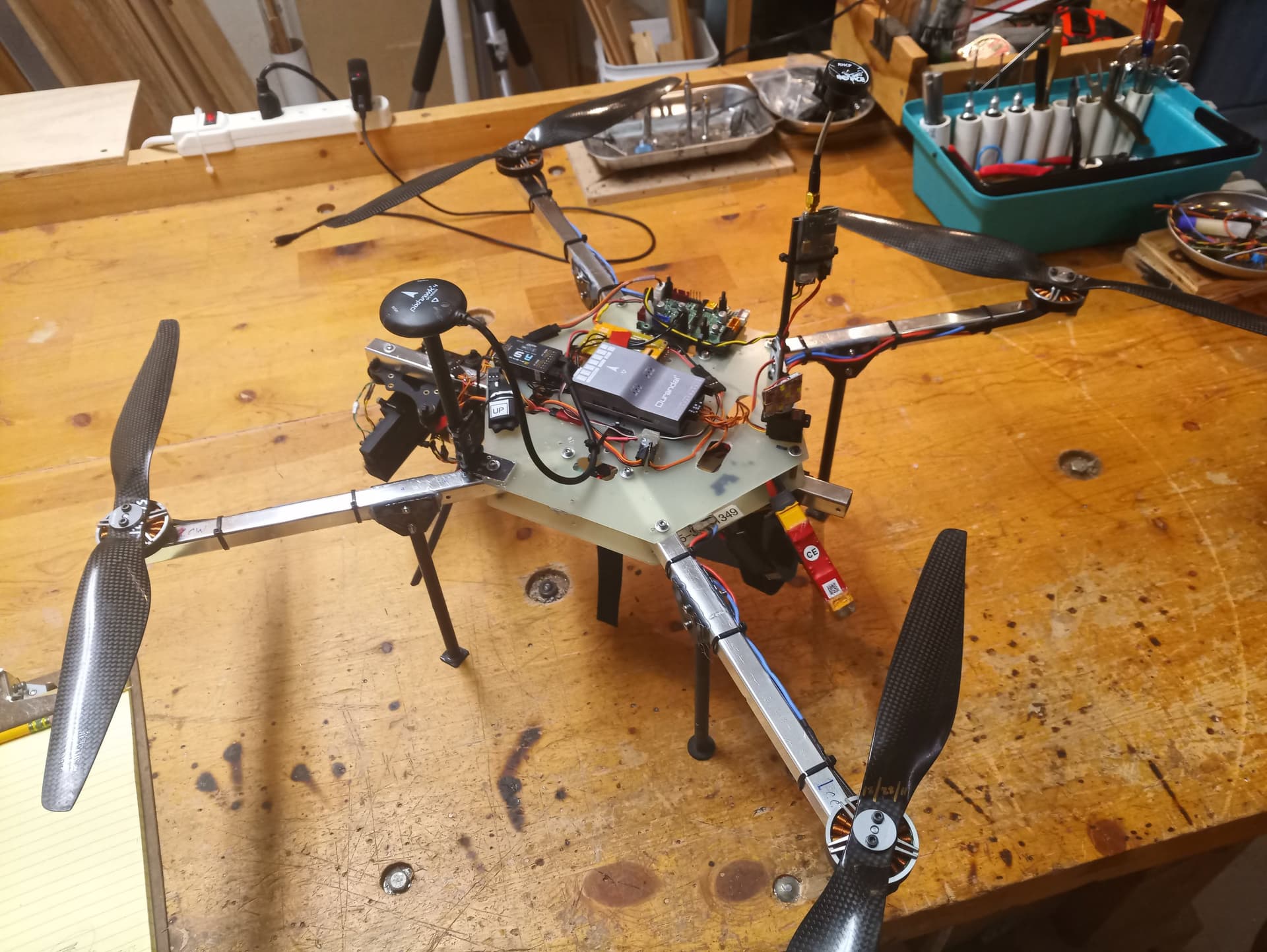
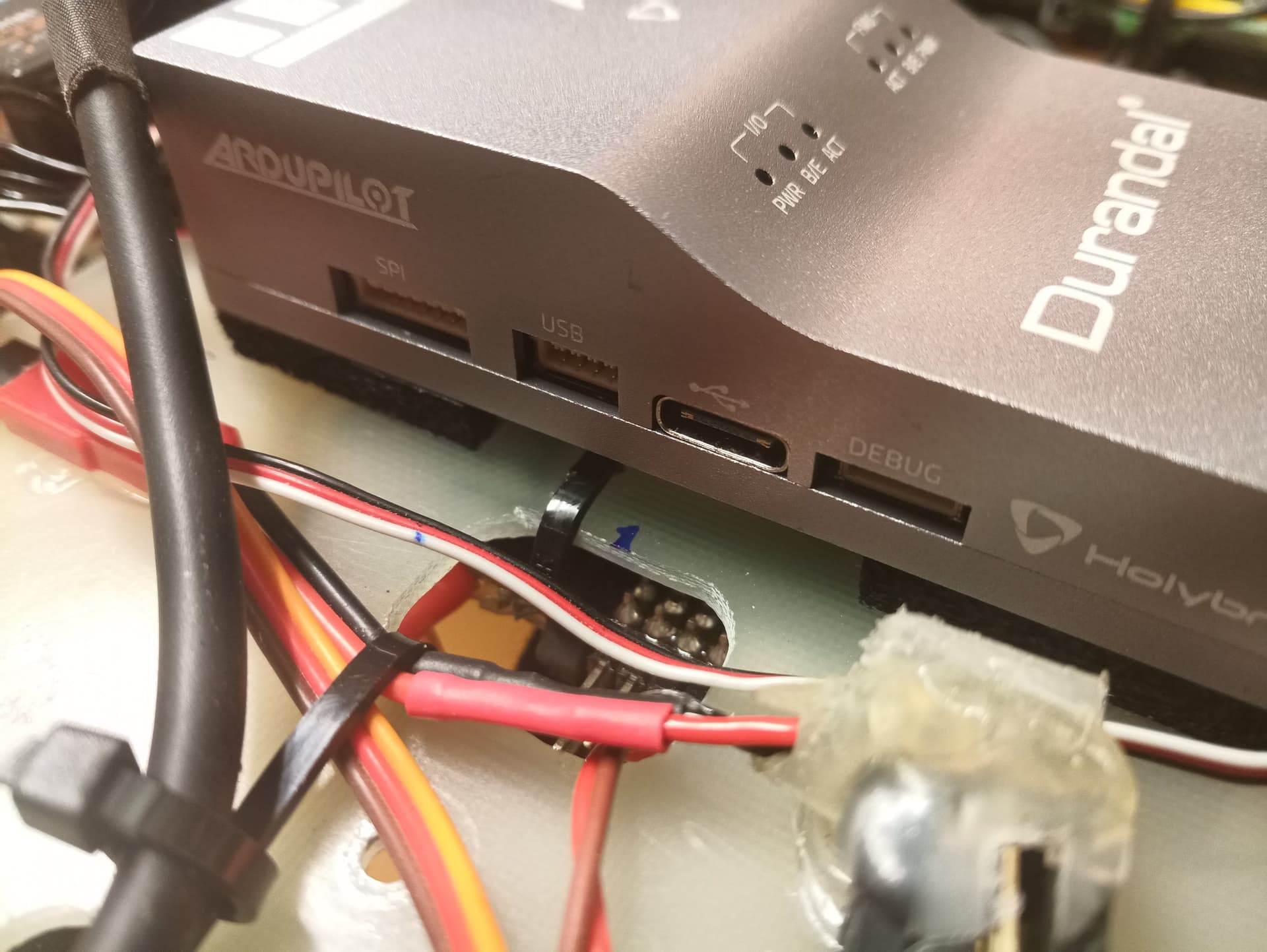
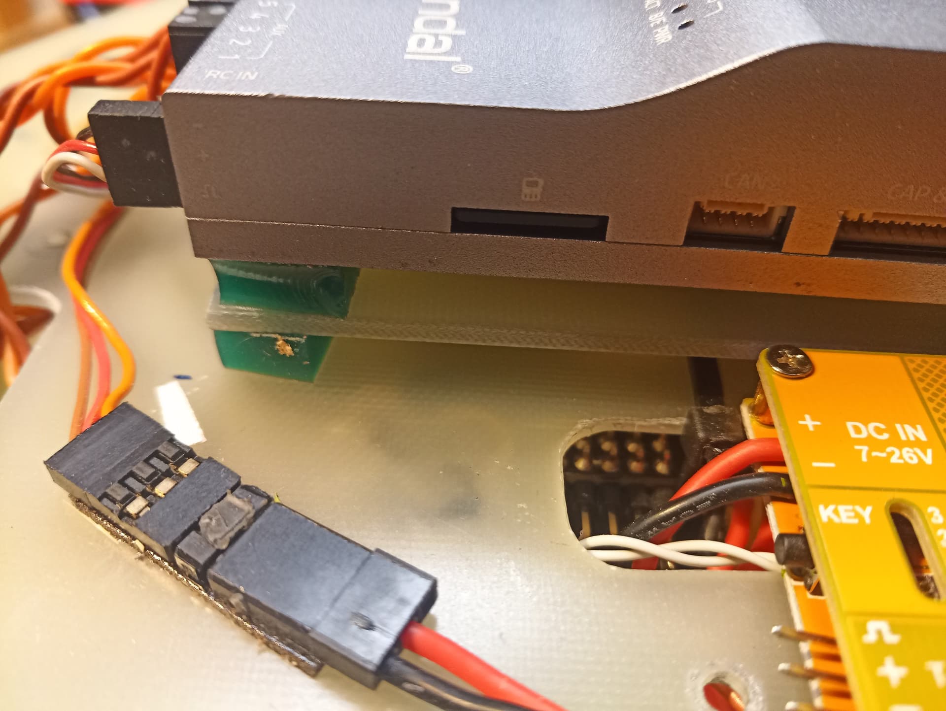
The FC is a Holybro Durandal, mounted via multiple layers of double-sided 3M tape, flashed with Copter 4.1.1.
I have:
-balanced the props - 15in T-motor style
-frame C.G. within 3mm of center
-compass was calibrated before I discovered all this Y axis vibration
-tightened the landing gear struts - there was some play after a few “stiff” landings. 4 struts about 150mm tall, 10mm CF tubes with pads on the ends
-checked torque on frame plate and arm screws, frame is very rigid
-the GPS puck is stand mounted with essentially no play unless I really push on it- about 120mm tall CF 10mm tube
-removed the VTX and mast to eliminate that possibility
-for fun, used a gimbal IMU on each arm, spun up each motor without a prop and checked the vibration with the gimbal controller board and GUI. Nothing crazy seen on any motor, even at 100% THR.
Your vibration levels are crazy high. they should be bellow 20. test some different FC mounting strategies, you double sided tape is not good at absorbing the vibrations
is it clipping? you can try to use *SMAX parameters to do some rate limiting on the outputs to avoid self oscillation, but It is better to solve the underlying hardware issue then to use software based workarounds.
This morning found I had routed the GPS cable across the top frame plate and an ESC was mounted exactly underneath on the bottom of the plate. Flew a check flight but that didn’t change anything.
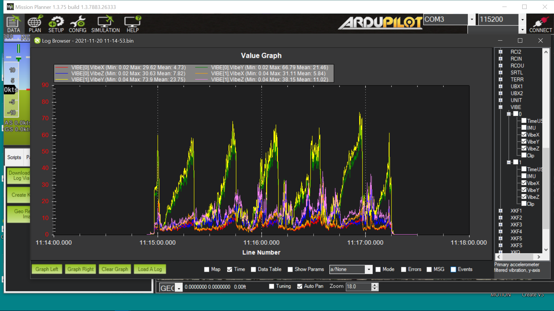
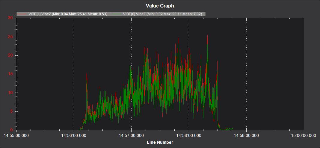
Then swapped out the tape layers for the OEM foam pads. As you can see, the vibe is significantly better but not nearly good enough. I suppose it’s time to look at filtering.
I am thinking your airframe may not be stiff enough. Would you be able to double the thickness of the top plate by just stacking another one? Might have to do something similar with the bottom as well…
I agree with @manavgandhi17 . We have seen frames like this before with aluminum arms and thin plates spaced close together. I think you will need much greater rigidity. Is that FR4 material for the plates?
These plates aren’t as thin as they probably look. They are 0.080"- slightly over 2mm, G10/FR4 board.
There is zero play between the plates and arms. The plates are CNC’d for perfect arm screw hole alignment - no slop. Inside the arms where the mounting screws go through, are printed support spacers so the screws can’t crush the arms. The motors attach in a similar way with spacers in the arm ends. All hardware is 3mm stainless with lock nuts. All have been checked/tightened.
If I was to put a number on the ability to deflect the arms across this frame, I’d say no more than 3-4mm, using significant effort.
Also, the frame plates are of a standard design and are flying on 2 larger 820mm hexacopters. Just a matter of which screw holes to use for 4 or 6 arms. No issues with either of those frames.
The baffling part of this is just the Y axis and the rhythmic nature of the vibration.
Those masts!
Cable tie the GPS wiring to the GPS mast and the base plate to stop the mat from vibrating.
The other radio mast can get the same treatment, in fact that 2nd mast may not be needed.
I would say you need something much more compliant for the mount than Zeal or foam tape. It must be severe for an FC with a well isolated IMU like the Durandal to be that bad. But your double plate mount does look better.
No need to rebuild. Just turn on logging when disarmed and through the autopilot on board with some sort of 5V power (you can even rig it off a portable battery pack. Would be interesting to see what vibrations values are measured by it.
A few days ago in this process, I used a gimbal IMU, mounted on each arm to analyse the vibrations. With no props on and the gear resting on a soft towel, I ran each motor up to full THR and in the gimbal’s GUI, I had to drop the scaling down to the lowest value to be able to see really any vibration.
In addition to your other FC idea to record the data, might run through that again with the double levels of isolation now installed.
I agree with you reference most vibrations come from out of balance props and/or the prop wash hitting the supporting arm, the vibration has to start someplace though and all motors aren’t perfect.
One thing we can all notice is that the majority of us use a 2 bladed prop. Two mounting holes on a motor that has 4 holes, like these SunnySky V4006s. So in essence, I can mount that prop 4 different directions. If a motor is even fractionally un-balanced, depending on the direction I mount the prop, a motor vibration can get better, have no affect or made worse, especially at the RPMs they run.
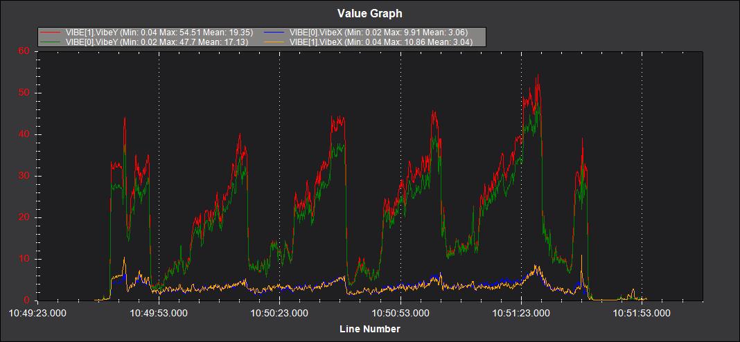
Here’s some data gathered today. I re-balanced the props, hovered 4 times, for 2min each flight, rotating the props 90deg on their respective motors in turn. Very calm conditions BTW.
PROP position #1 VIBE1-3.36 VIBE0-2.84
PROP position #2 VIBE1-3.19 VIBE0-2.77
PROP position #3 VIBE1-4.09 VIBE0-3.35
PROP position #4 VIBE1-3.52 VIBE0-2.97
These are the “mean” values for Y axis, so I’ll be moving the props back to the #2 position based on this data.
Since it’s a nice holiday here in the U.S., I’ll relate a real life story to this very point.
I talked with a helicopter pilot years ago who was convalescing from a crash. The engine quit on him while sling-loading Christmas trees. Aircraft was destroyed.
The investigation revealed a vibration caused a valve in the hydro-mechanical fuel control to fail. The vibration was caused by the misplacement of the starter generator on the engine gear box, where the fuel control is also mounted. You see, the generator has a square mounting hole pattern, so it can be mounted in 4 directions. The procedure is to mount the generator, place a vibration meter on it and run the engine. It the vibration exceeds X, then rotate the generator 90deg and re-mount. Do that until you get the lowest vibration.