Cross posted from Hardware > Pixhawk family, didn’t get a response there but I’m on V4 and people seem helpful for this kind of problem on this thread so…
Hi Guys,
Been tinkering with arduplane for a while now and had an FX61 flying nicely with a Chinese PIXHAWK kit but found it difficult to work with ad-hoc because I needed more space for things like a companion computer and other stuff so I bought a rambler RS PNP on special offer and moved everything over. I’m using the motor and ESC supplied with the rambler rather than the setup I had on the FX61 (Turnigy plush-32 & sunnysky X2216). I’ getting ugly current readings from the new setup. I suspect the ESC and have a selection of ESCs I could try (though not the one from the phoenix as this is buried in my fun plane).
Here are some graphs for comparison :
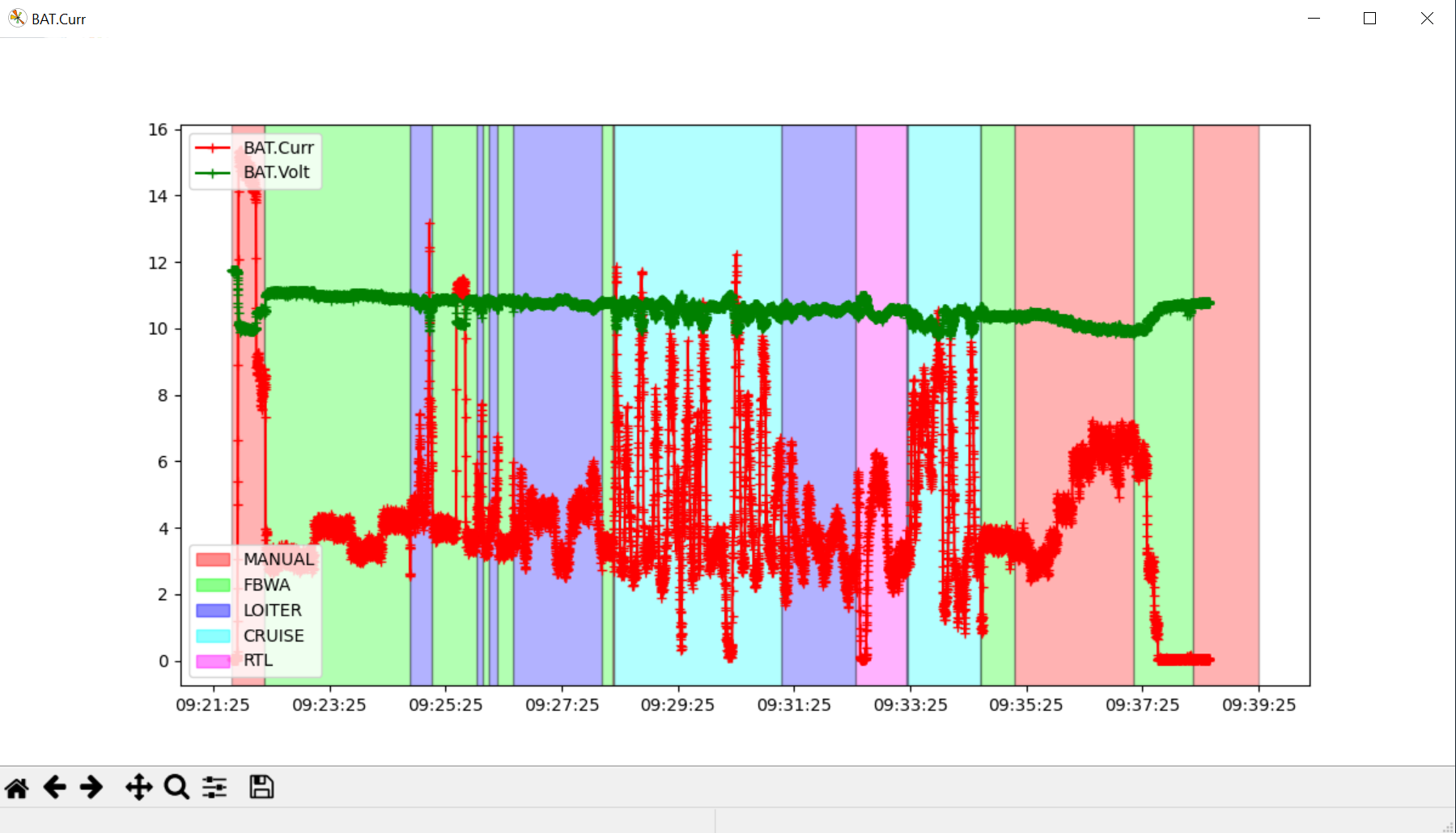
Graph 1 : Example flight phoenix Current and Voltage
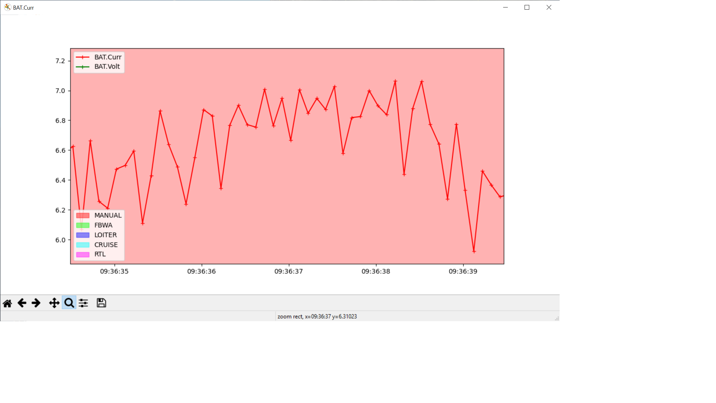
Anyone out there just seen this before ? It kind of looks like a quantisation thing but then how does the current sensor deal with the on/off nature of an ESC ?
I also have an oscilloscope (picoscope, the basic one) available to me. Where would people suggest I start prodding ?
Plot the current against the throttle output or the motor channel. See how those compare to one another. More or less they should trend the same way as the motor will likely be your highest draw.
If the motor output is that jumpy, then it could be a sign that the pitch tuning on this plane isn’t as good as it could be. Modes like Loiter and cruise will use the throttle to help manage altitude.
If the motor output is nice and smooth against that jumpy current draw then have a look at the hardware. Loose or damaged prop? Bad wiring or cold solder join? Or just poor quality PNP parts.
Is that a LiPo battery or LiIon? If it’s LiPo the voltage is getting low and you may be running into sag issues.
Thanks for taking the time to reply.
OK, had another good look at it last night and everything seemed fine, the glitches disappeared but this was with the fuse on the bench with no servos attached. Went back this morning and assembled the plane, connected the servos and the the problem re-appeared. Disconnected the servos again, problem still there. Disconnected the power module and WD40’d the connector and the problem disappeared. Tested a couple of times OK.
Do you know if this is the sort of behavior I would expect from a poor quality connection ?
It’s a LiIon battery and all the tests I did last night were in manual mode on the bench so not a SW issue.
Thanks again for the input.
I also wouldn’t recommend using WD40 on electrical connections. It works as a cleaner, but then leaves behind a residue that will actually increase resistance.
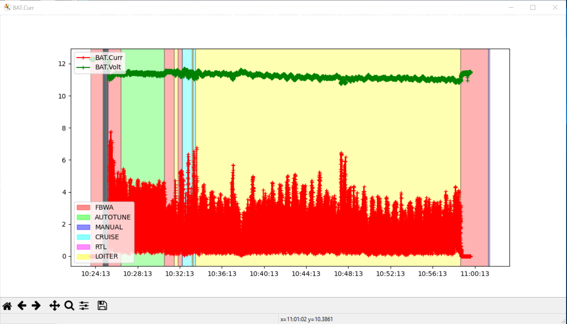
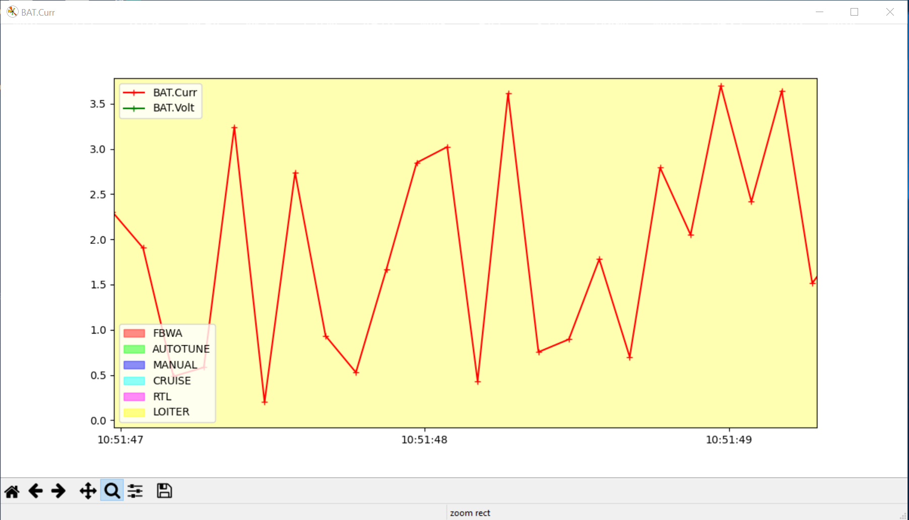
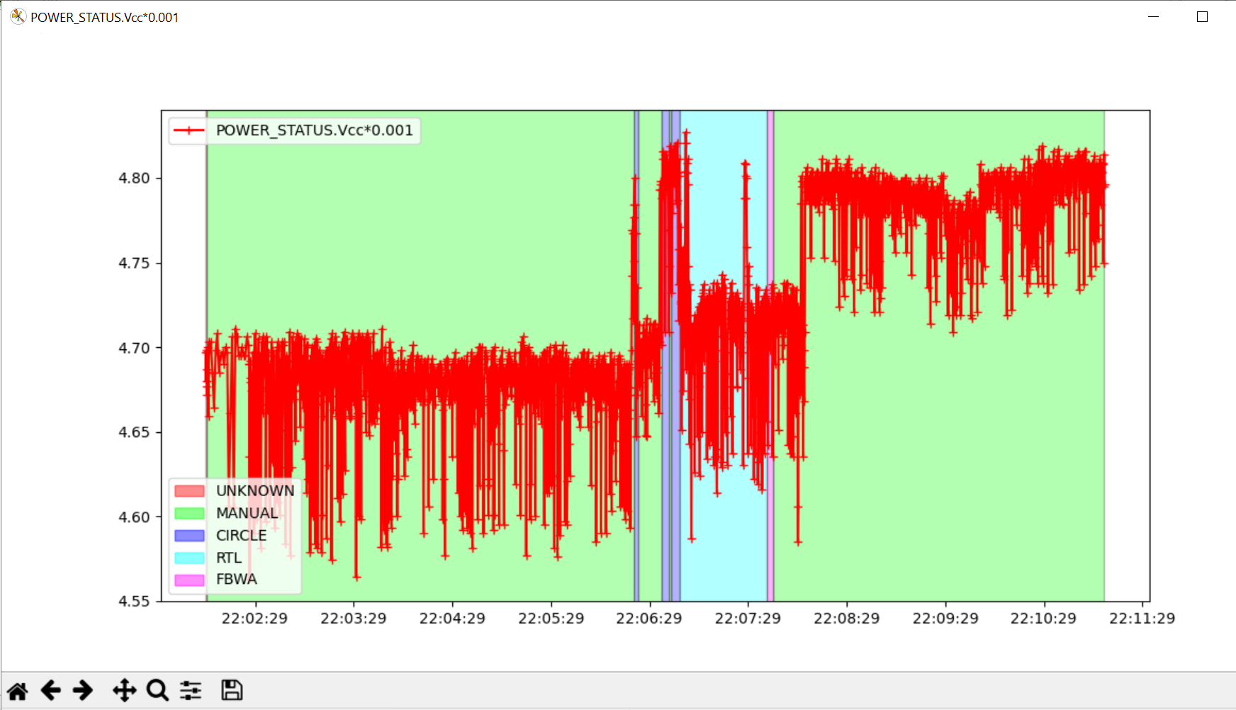
Curiouser and curiouser, the output of the ESC is 5.00V, the power module 5.2V (with the plane booted up). When I measured Vcc on a telem port I got 4.85V. I stumbled upon a pre defined graph in MAVExplorer and got this :
Is this enough to trigger a brown out or switch to the servo power input ? I’ve not had any avionics power warnings. Also confused by the different power consumptions in different modes, I think the RC connector kicked off the Circle/RTL portion (this is all on the bench) but the voltage readings change then in the second portion of manual mode…