Good morning, I am using a pixhawk orange cube with a holybro F9P GPS receiver.
I am attempting to switch over from a can based GPS module (Here 3) to a holybro F9P GPS. I have plugged in the GPS module to the UART to USB connector, then ran wires off of that convertor to my GPS 2 port. Mission planner has picked up an external compass so I know that it realizes that the GPS is now connected to the pixhawk board, however the HUD screen still says “no gps”. I have switched Serial4=5 and the baud rate to 115. The blue lights on the GPS module are blinking so I know the GPS itself is working, as well as the flashing blue lights that will let me arm my rover and drive it in manual mode. However, like I said, the HUD still remains with “no gps”
Any help on this topic would be greatly appreciated.
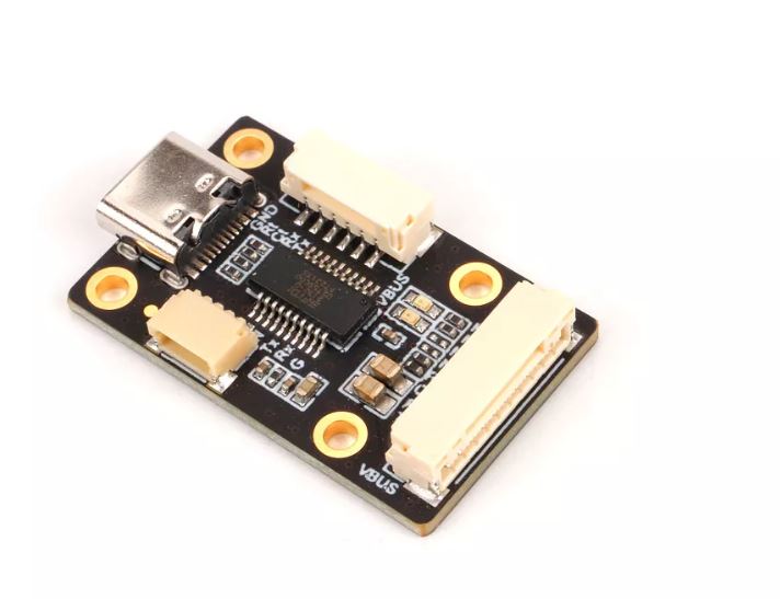
There is a breakout section on the converter. It has a usb connector at the end of it, as well as a 4 pin breakout and a 6 pin breakout. I chose to use the 6pin breakout because that is what the GPS2 port uses as well.
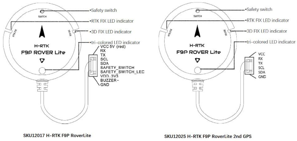
It is the left GPS that is shown in your picture above @Webillo . However, the 10 pin connector shown does not plug directly into my pixhawk orange cube. The pixhawk orange cube has an 8 pin plug for “GPS1” and a 6 pin plug for “GPS2”. Because of this, I use a converter that came with the GPS (pictured below). I use the 6 pin breakout of this board and plug it directly into the 6 pin “GPS2” port on my pixhawk orange cube. Can I do this? Or am I missing something that does not allow me to do this? I have changed the “Serial 4” parameter to 5 on mission planner so it is configured as a GPS module on there. The blue LED works and I can drive it in manual mode, but it still keeps giving me the “No GPS” message in the HUD. Thank you again for your time and I hope this explanation makes a little bit more sense!
No. I suppose that board (essentially USB to serial) is meant for testing a GPS with u-blox u-center program (try it).
Suppose the uart transmit signal from the FC to the receive signal on the GPS. Possibly you are connecting them, but also to a transmit signal on the FTDI chip, so you are making a short.
You could unsolder the chip, and perhaps that would work, but try to use things for their meant purpose and conserve that board. Look for a passive solution (without active components) for your problem; I have no experience on Cubes (the GPS on the left connects directly to the Pixhawk 4 (GPS/compass/buzzer/switch/led on one connector)), but other people should know.
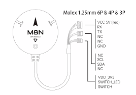
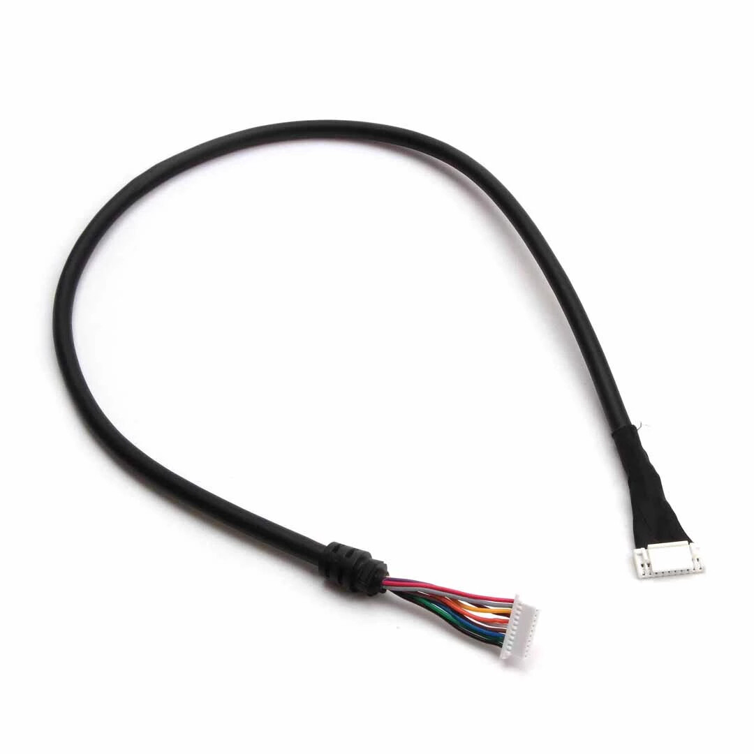
Perhaps you can open the GPS and substitute the cable with a DIY one: