Hello,
in case anyone is interested here are a few photos and points from a newbie skid/differential build. This one is for fun and experience ahead of building a more serious agbot for weed spraying.
Hopefully it gives some idea about getting everything working. Most of the work was done this weekend.
Apart from Pixhawk component decisions were mostly what I had lying around.
Ingredients:
- Pixhawk 2.4.8 from eBay
- Cheap cordless drills from eBay (incl. battery pack), qty: 2
- uBlox M8T on (GY-GPSV3-M8T from aliexpress, already had) using the stock antenna and junk CD for ground plate
- ESP8266 NodeMCU for telemetry
- Cytron MD13s, qty: 2. [I originally planned to transplant the MOSFETs from the drills but decided for £9 it wasn’t worth it]
- old Meccano wheels and scrap wood for chassis
- XBox controller
- QGroundControl (as I’m on Linux and couldn’t be bothered fiddling with Wine/Mono)
- No radio
Drive
I got cheap cordless drills from eBay on the basis that motor, gearbox, MOSFET/controller and even battery/charger would be useful and the posted price is same ballpark as bare RS-550 motors. Incidentally, these drills would be awful for even basic DIY work. I am always striving to be more environmentally friendly and feel bad I have supported this market.
Drills were gutted. Battery pack (3x 18650) and charging circuitry were kept intact.
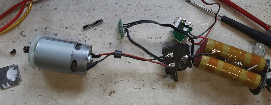
A cursory attempt to reuse the MOSFET by resoldering it onto a basic circuit and playing with Arduino was made.
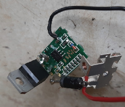
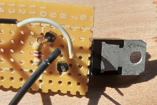
That idea was hastily forgotten and 2x Cytron MD13S were ordered. It’s important to note these controllers peak is 30A, which I already knew was below the RS550 motor’s stall draw. In other words, care is needed and in future I’d just get a higher capacity controller.
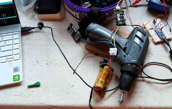
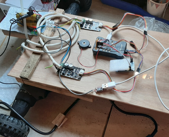
Drill casing (looks like ABS) was screwed to block of wood, and then reassembled with only the motor/gearbox/chuck inside and the motor wire hanging out. The Cytron controller would fit where the battery previously was but the wires to the motor weren’t quite long enough and desoldering them just to make them a little longer felt too much effort. Motors+controllers were tested with Arduino, and yes hitting the power quickly did cause the Cytron’s over current warning like to flick on.
Chassis
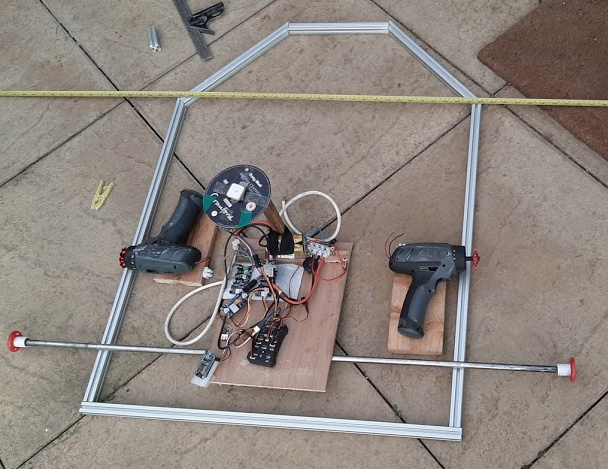
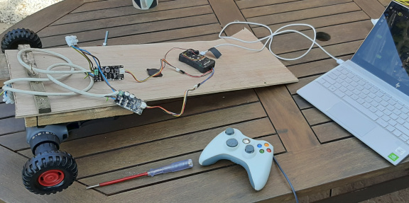
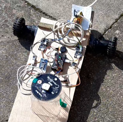
The drill drive units were screwed to scrap plywood base with extra brace. Meccano wheels with hubs removed were bolted through (not yet in photo below) and tightened in drill chuck (both nuts and chuck would regularly come loose- big frustration and definitely the next thing to be changed!).
Initial setup and sanity check
At this stage I connected the Pixhawk for the first time and did basic setup in QGroundControl. The help guide https://ardupilot.org/rover/ was super helpful. For the Cytron one needs BrushedWithRelay motors, setting ThrottleLeft and ThrottleRight Servo functions. Direction by default are AUX5,6 (not actually connected in photo above).
I set the max throttle to the lowest possible (30%) as I knew this would already be fast enough (from the Arduino tests) and would not cause the OC warning to trigger. Also the motor slew rate. A word of caution is that when manually controlling the motors (Manual or Test) the max does not seem to be applied.
I calibrated an XBox controller to test things out. Arming checks need tinkering with in order to play without an radio. A slightly confusing point is that in QGroundControl the left and right motors respond under “Motor C” and Motor D". Anyway, it was reassuring to see everything working.
First drive and ESP8266 telemetry
Connected to laptop with USB and holding XBox controller. Not recommended! At this stage the robot was basically a taildragger and a castor wheel was deemed necessary.
Fortunately I remembered having some ESP8266s. Flashed and connected according to instructions somewhere on the Ardupilot site (link to be added). Had to butcher one of the little 1.25mm pitch cables and solder to normal 2.54mm header. Also added a 5v regulator with USB socket. Note battery being charge in situ ready for action. Components are stuck down with glue gun.
Adding GPS
The uBlox M8T can be used with RTK by using RTK lib. My final rover will include a Jetson Nano and this is no problem. For this test the M8T is connected directly to the Pixhawk and no RTK is used. After setting the protocol to uBlox and getting the right baud the module worked fine. Again I just soldered onto 2.54mm header. An old CD was used as grounding plate, which seemed to have helped in past experiments. It was mounted on an strawberry box and sellotaped to the plywood chassis.
Maiden GPS guided voyage
Warmed up by doing a few laps of the drive with XBox controller (Acro mode). The steering was pretty good “out of the box” but I did make a few tweaks after watching Randy’s videos on youtube (TODO add link) and probably need more.
When not moving the robot tends to shudder a little but it’s fine when moving. This probably needs parameter tweaks too.
The initial attempt at a simple GPS mission was a disaster. The robot kept trying to turn the wrong way. In QGroundControl I spotted the orientation was way out. The calibration had been done before mounting but now perhaps being affected by the motors? Anyway after re-doing the compass calibration it worked well and I was quite pleased!
Next steps
Almost everything needs to be improved before it’s ready for field testing.
- Better power management, better cabling and XT60 connectors (already ordered) and bigger battery (say 110Ah, ~20kg, should give 7-8 hrs work)
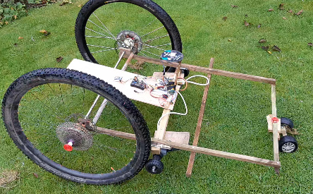
- Wheels to be upgraded to mountain bike (29er) wheels
- Jetson Nano mounted and RTK
etc