Hi all,
unfortunately it didn’t perform any better than the VL53L1x. In low light it works well, in direct sunlight the behavior was not good, making the quad unstable and I also had to land in an emergency because I didn’t have good control. On the Yappu telemetry the reading seemed correct. Also, I have mounted TF luna on a piece of copper PCB but the GPS doesn’t work well (didn’t see any satellite in over 10 minutes of flight).
I also used the auxiliary function to switch off the lidar, but it doesn’t seem to work.
CH13 OPT 10
https://ardupilot.org/copter/docs/common-auxiliary-functions.html
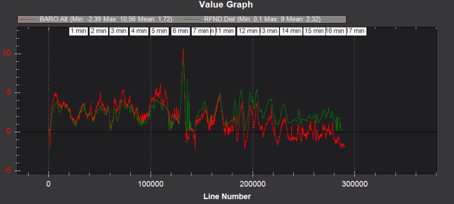
I attach the flight log if anyone has any suggestions, thanks
https://drive.google.com/file/d/1WTaUe8nHfsY8835HbvFl-bqd7JW1axjd/view?usp=sharing