I’d be down too, location and missus permitting. Would like to work on mine some more but have three kiddos now.
A very common GPS unit used on these mowers is the full size ArduSimple SimpleRTK2B boards. These also use F9P chips and they work well with the Ardupilot system, including the automatic configuration process, which keeps the configuration parameters on the GPS boards set correctly when firmware updates come out for the flight controller. The RTK2B boards probably cost a bit less than the Holybro DroneCan F9P GPS units. The DroneCan units do look more like a finished product though, rather than a board you have to mount. I use 2 of the ArduSimple boards in my mower and a 3rd one as my fixed base inside my GPS base station.
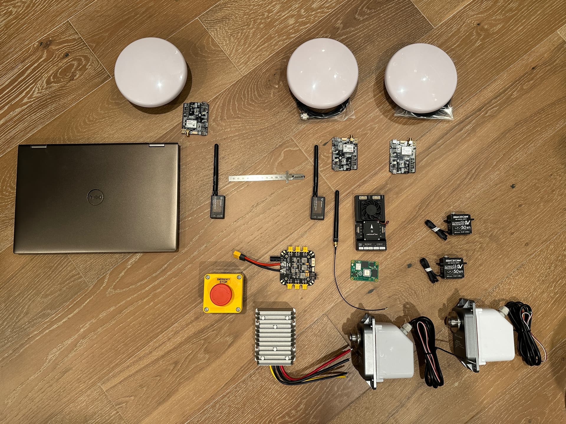
Just followed your lead @SJohnson, and @Yuri_Rage advice in the “best-gear-for-starting-ardupilot-mower” thread. Here are the GPS (starting) components:
Budget Survey GNSS Multiband antenna (IP66)](https://www.ardusimple.com/product/survey-gnss-multiband-antenna/)× 3 |USD $97.90ea|
simpleRTK2B Pro (https://www.ardusimple.com/product/simplertk2b-pro/?attribute_pa_header-options=without-headers&attribute_pa_zed-f9-variant=zed-f9p) × 3 |USD 248.60ea|
USD $1,039.50
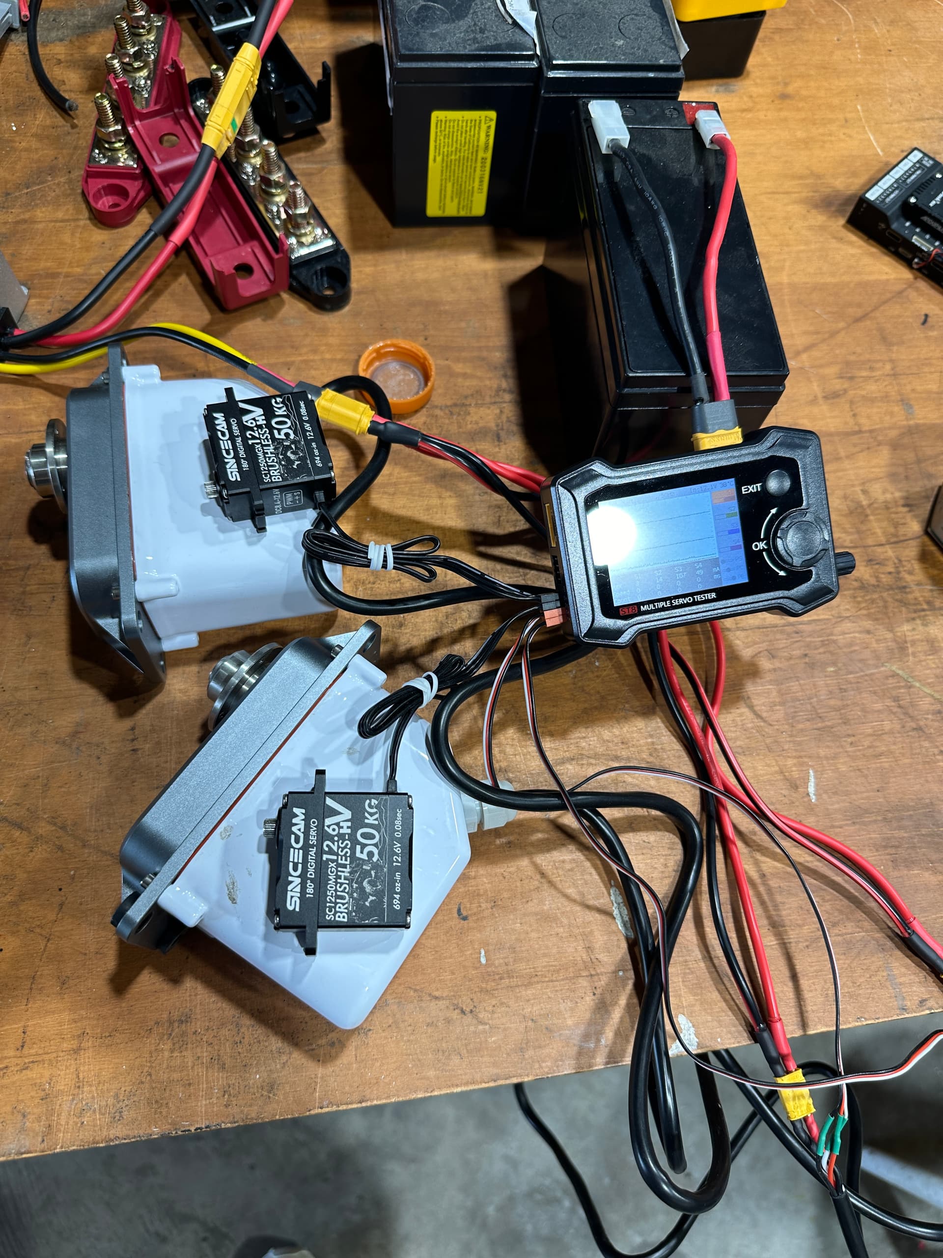
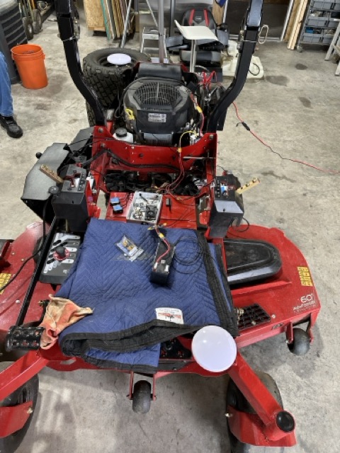
I think I have most of my position/telemetry/electro-mechanicals (but no mounting adapters yet). Take a look at the pic, and let me know if I’m missing anything (other than the battery, wires. . .). I may have ordered too many telemetry radios - should I have 4 units? I just place the 2 I thought I’d need in the pic.
Also, placed a steel ruler between the telemetry radios so you could get an idea of scale - the 400kg servos are giant next to the throttle/choke servos. . .
cris. . .
2 Likes
Looks like you’re in bidness! Now the fun begins!
1 Like
How many 915Mhz radios you need depends on how you configure your overall system.
You need 2 matched radios (same ID code) in each one so they only talk to each other, for the main Telemetry from the mower back to Mission Planner.
If you need the other pair of radios or not depends on how you deliver the RTCM3 signal from the fixed base over to either Mission Planner or over to the moving base in the mower directly without going through Mission Planner. If your fixed base (GNSS Base Station) plugs into the computer running Mission Planner over USB, you don’t need the other 2 radios.
Yuri posted this earlier that could help.
1 Like
Yuri - I went big upon your advice - fabricating the mounts now, and have a location in order - thanks as usual for all for the advice…cd
I have fully tested my power system on the bench - will think about physically locating it after Mowstock when I’ve had a chance to see what/how others are powereing their equipment. I used a nice little servo “tester” and have a home for the Happy400 servos - just some fabrication of the mounts and cable routing left to do.
For the Flight Controller, the telemetry went in without a hitch, and the Fixed Base GPS via the Mission Planner computer serial port is working fine (once I found the DroneID panel).
Yaw configuration is confusing me entirely. Not sure how I got the Moving Base working, but it had something to do with @Yuri_Rage 's comments on auto config of the SimpleRTK (without heading) units.
I still don’t understand how to identify the serial ports on my Pixhawk 6 Rpi. I went with Telem3/Serial_3 and GPS2/Serial_5. GPS2 is working, but nada from GPS1 in the Telem3 port (Telem2 is reserved for coms with the Rpi as I understand the documentation - I’m not intending on using the Rpi yet, so no work done there).
My questions are around what actually configures the serial ports, and how will the configuration expose itself as working?
To configure, is it Setup::Mandatory Hardware::Serial Ports? Or, Config::Full Parameter List::SerialX::Baud/Options/Protocol? Something else?
To know something is working from the Flight Controller or Mission Planner, is it the HUD::Lower Left::GPS:No GPS, GPS2:3D dgps? Or, configuring the Quick menu to show GPS status? Or somewhere else?
I’ll bring my gear (not the mower) to Mowstock, but any pointers in the interim much appreciated - I feel like the Pixhawk 6 Rpi is configured slightly different that the threads I’ve been reading.
Have a great week! cd…
1 Like
I don’t know what a “Pixhawk 6 RPi” is. Provide a specific link to the product you’re using, and I may be able to help.
Also save and attach a copy of your current parameters.
1 Like
We will help you sort this stuff out at MowStock. It sounds like some parameters are wrong and are easily fixed after we understand the details.
1 Like
Some build pics:
Side view of Toro with linkages:
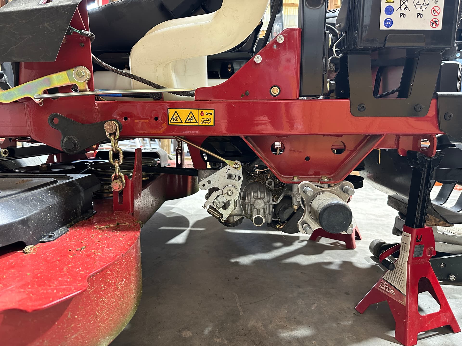
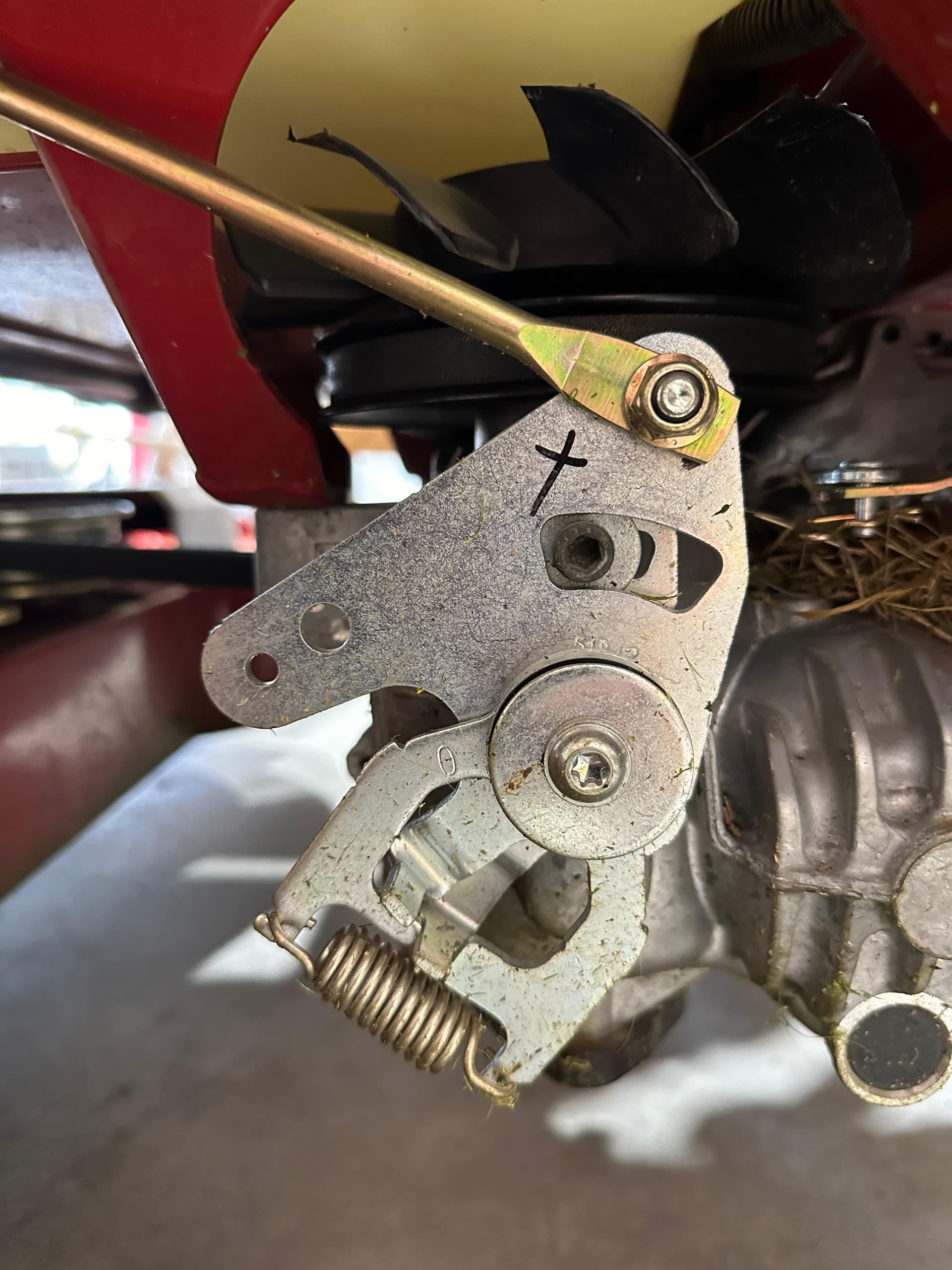
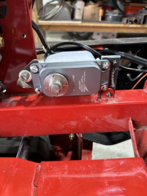
Close up of linkage to hydrostatic drive with possible attach points (not the X, but the existing 2 holes on the left end of the tab:
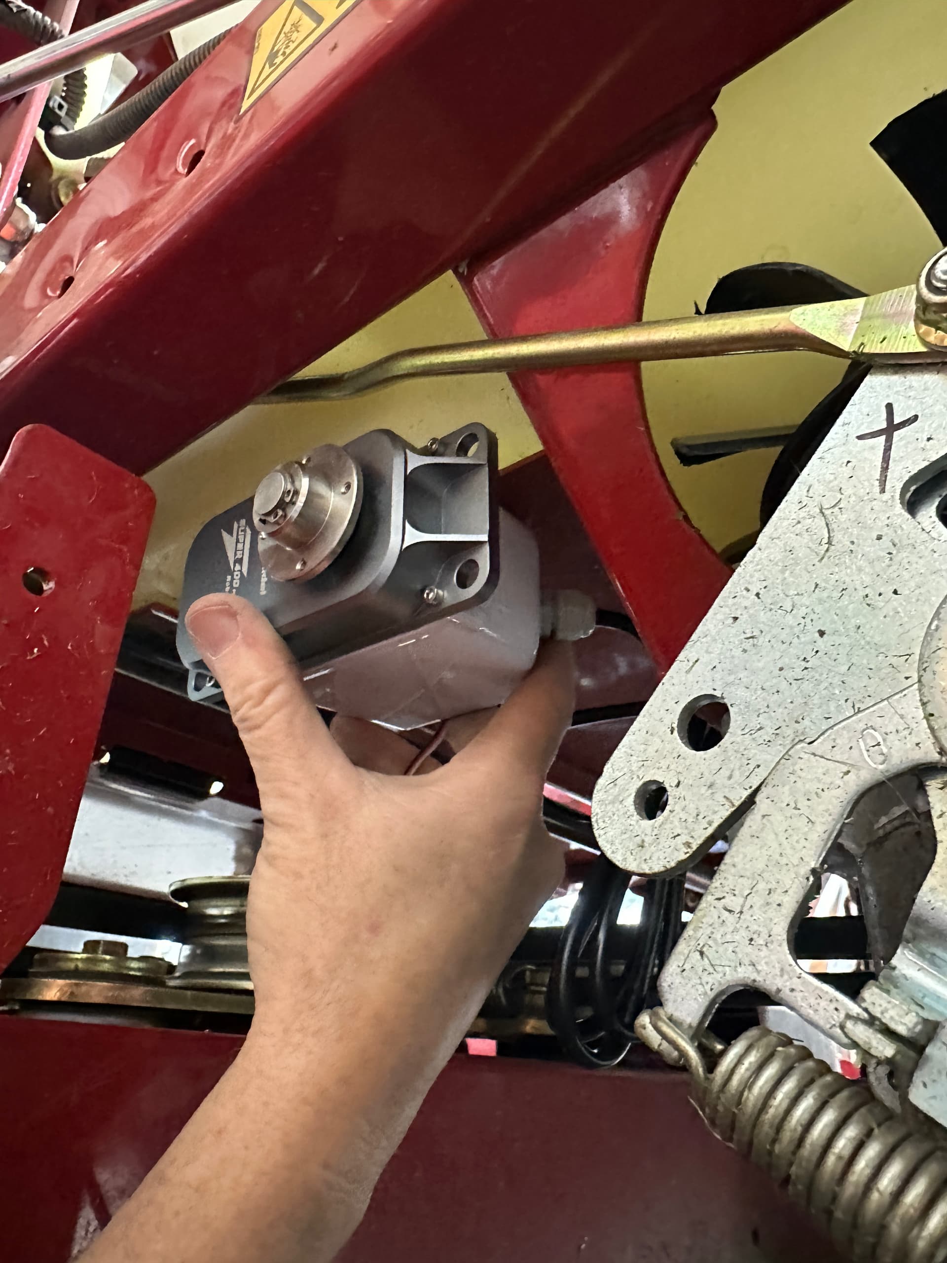
Hand holding the servo near the mount point:
Power testing with servo tester:
Telem1 is where I have my radio plugged in; Telem3 is where I physically connected to the Moving Base GPS - Assumed to be SERIAL_3
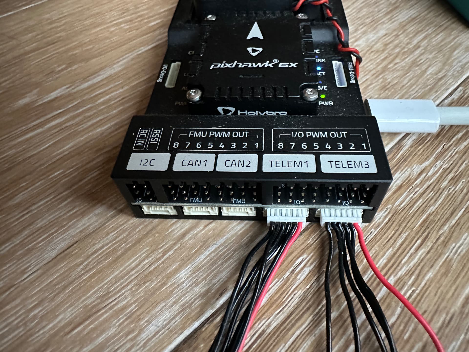
GPS2 is connected to the Rover GPS - Assumed to be SERIAL_5. I’ve been thinking about building a cable to attach the first GPS unit to GPS1 - something tells me this will solve my issues - should have that done later today.
Was hoping you’d say that. Looking forward to meeting!
Serial port mapping is here:
Pixhawk 6X Flight Controller — Rover documentation (ardupilot.org)
The autopilot is a Holybro Pixhawk 6X.
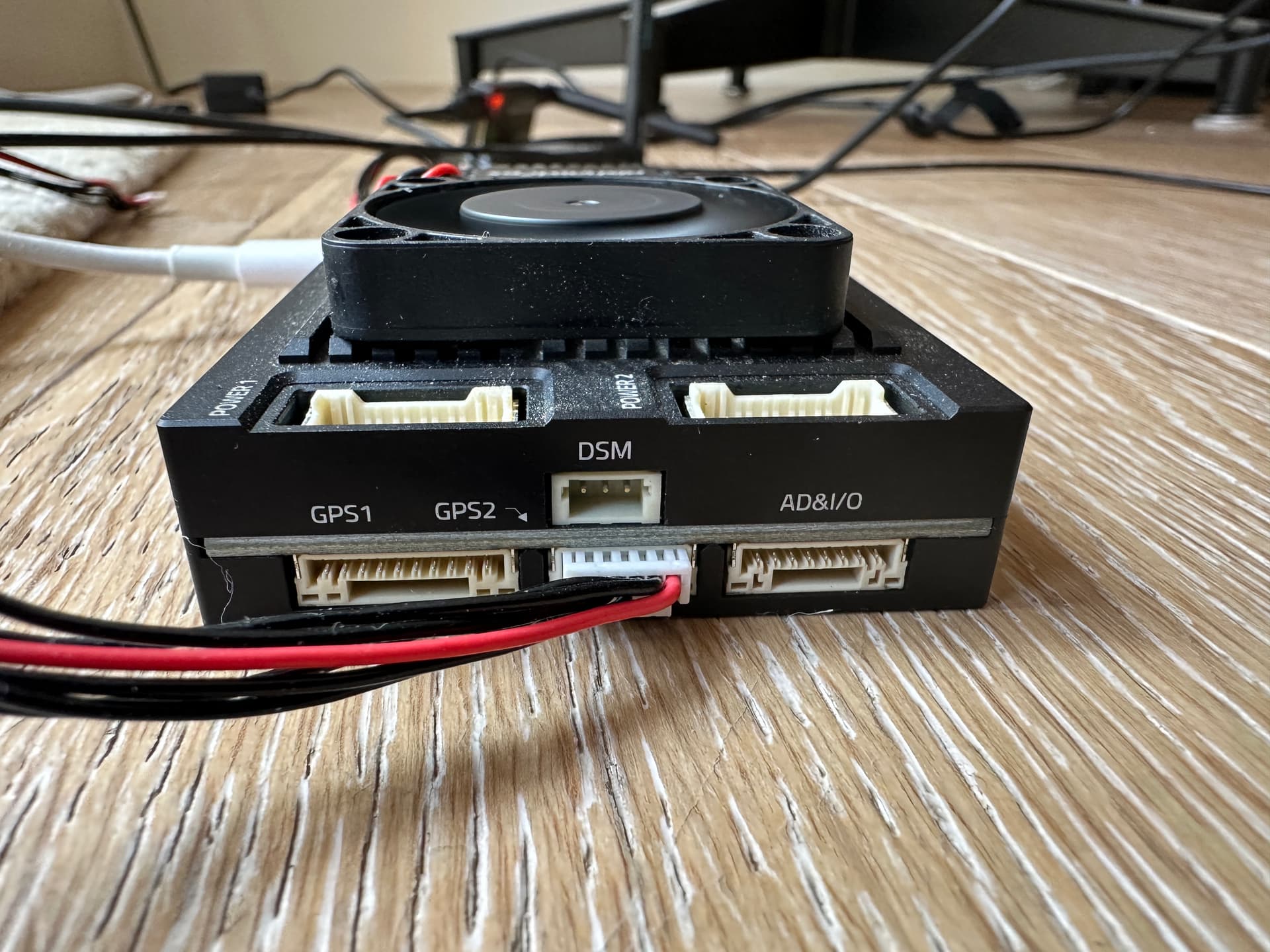
The carrier board contains a Raspberry Pi compute module that renders Telem2 (SERIAL2) useless for anything other than communication between the compute module and the autopilot.
Share the labels on the ports where your GPS modules are presently connected as well as your current param file, and I’ll likely have you sorted.
Might also help to see a pic of the GPS modules and their wiring.
1 Like
Hey @Yuri_Rage, I got them talking - made the cable for attachment to GPS1, and everything fell into place. I’ll need some help with the tuning, but hope to absorb a bunch this weekend.
Again, thanks for all you contribute to this forum! Cd…
1 Like
Your attachment point to the hydro drive is fine, just remove the spring below it and you’re on your way. See you this weekend!
1 Like
Forgot to mention - you found the exact UART Mapping I needed - I focused too much on the drawing above the map. . . cd
UART Mapping
- SERIALO → USB
*** SERIAL1 → UART7 (Telem1) RTS/CTS pins** - SERIAL2 → UART5 (Telem2) RTS/CTS pins
*** SERIAL3 → USART1 (GPS1)**
*** SERIAL4 → UART8 (GPS2)** - SERIALS → USART2 (Telem3) RTS/CTS pins
- SERIAL6 → UART4 (User)
- SERIAL7 → USART3 (Debug)
- SERIAL8 → USB (MAVLink, can be used for SLCAN with protocol change)
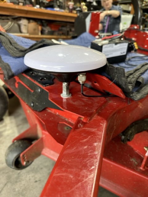
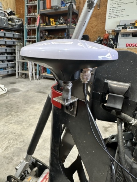
Removed the fuel tank to get closer to mount points, but found better locations. Installed GPS antennas. Have power to big servos directly from 12->24v converter.
Now routing wires, considering the interlocks, and configuring yaw settings!
1 Like
Hey Chris, it looks like you are making great progress. The mower is coming together! That Toro makes a really good platform.
Also I wanted to mention that I ordered a long range remote “kill switch” on Amazon that I will be installing on my mower in addition to the “kill switch” operated by the RC transmitter. I have run into situations where the power was interrupted to the receiver and/or the flight controller. To have an independent switch as a backup seems justified.
https://www.amazon.com/gp/product/B09B6MRMNL/ref=ppx_yo_dt_b_asin_title_o00_s00?ie=UTF8&th=1
1 Like
Forgot to add, one of my design goals is to use existing holes, wiring, linkages as possible. Turns out the safety interlock “looks” reasonably adaptable to our use case.
I’ve pulled the seat, removed the fuel tank, and plan to mount my controllers, gps radios where the fuel tank used to reside. I’ve ordered a tank aka @Swebre2023 ’s cub cadet rig to push some weight forward of cg now that I won’t be onboard.
Telemetry antenna mount is next (ok, one of the “nexts”)…cd
1 Like