Life takes sudden twists and turns. I had just done four flights with a F550 Hex in several modes. I tested it in STABILIZE, ALTITUDE, LOITER, and AUTO, and everything went well. I assumed the drone was now flight worthy. So I decided to do another AUTO (MISSION) on the 5th flight, and it was a fly away! Luckily it hit a tree nearby and didn’t get too far.
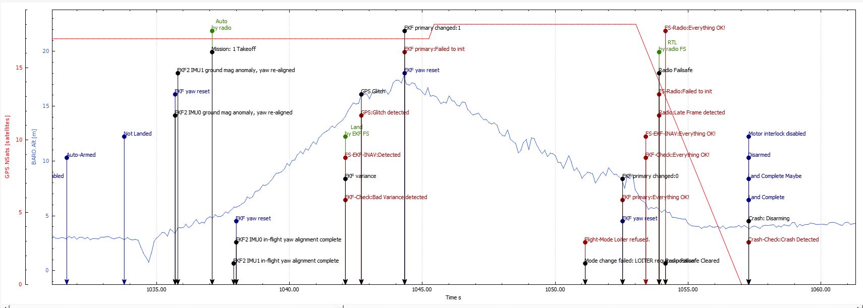
Here’s the flight log. I’d appreciate any feedback on exactly what happened.
GPS glitched causing a Land Failsafe then the GPS quits altogether (when it hit the tree?). Land w/o GPS is essentially decent in AltHold and it will drift with the wind w/o a position estimate.
Towards the end of the flight the hexa looses altitude but the apm go up very high and battery voltage keeps sinking. Towards the end with 780 watt it sinks while before that it was hovering at 360 watt. I think something was going on with power too. I agree on magetometer impacted everytime power was raising.
If that is the actual copter, then why there is only one MAG in the log ?
It seems that the compass on the GPS (if there is any) is not detected at all.
Right. Let’s see a screen capture of the HW ID screen in Mission Planner. @drone-av8r
Setup>Mandatory Hardware>HW ID
Internal compass=Bad placement. Sandwiched between the top and bottom plate on one of these F550 frames isn’t helping if it’s only the internal one being used. Batteries overhead, PDB below…
I have a VERY simillar configuration, F550 with pixhawk sandwiched in between plates and battery on top, and have done extensive testing in all most all modes (about 10 -15 hrs) and I can say with absolute certanity that it works great, poshold and loiter are rock solid.
Should I be concerned though… ?
It could be a bad mag calibration…
[Edit]: I havent done much tuning, only PIDS, and that too slightly. Mostly defualt params. I also have ony done a normal MAG calibration, no Motor / compass calibration yet…
That’s not the point. If you reviewed his parameter file you will find there is only one magnetometer being recognized and by Device ID it’s on the SPI bus. What does that mean? It’s the FC internal compass and at best those can be problematic and at worst, like this configuration, it can be useless. The problem isn’t that the FC is mounted between the frame plates (I had one like that) it’s that it’s only using the FC internal compass that is mounted between the frame plates.
The root of problem here is the external compass is not active.
Back again. I am aware that we are only using the compass in the FC. I have been flying these drones this way for over 2 years and do not have compass problems. The one time I connected the external compass it flew away, so I never used that configuration again.
Although you say this was not a GPS issue, I need to point something out. Ever since I started using ArduCopter, the drones have been plagued by the ever present “Bad GPS signal health” message I keep seeing. The GPS data rate is set at 5 HZ, and the GPS baudrate is set at 115 K. That should work fine. I don’t know what to do to get rid of this error message, but I think it might have something to do with the flyaway.
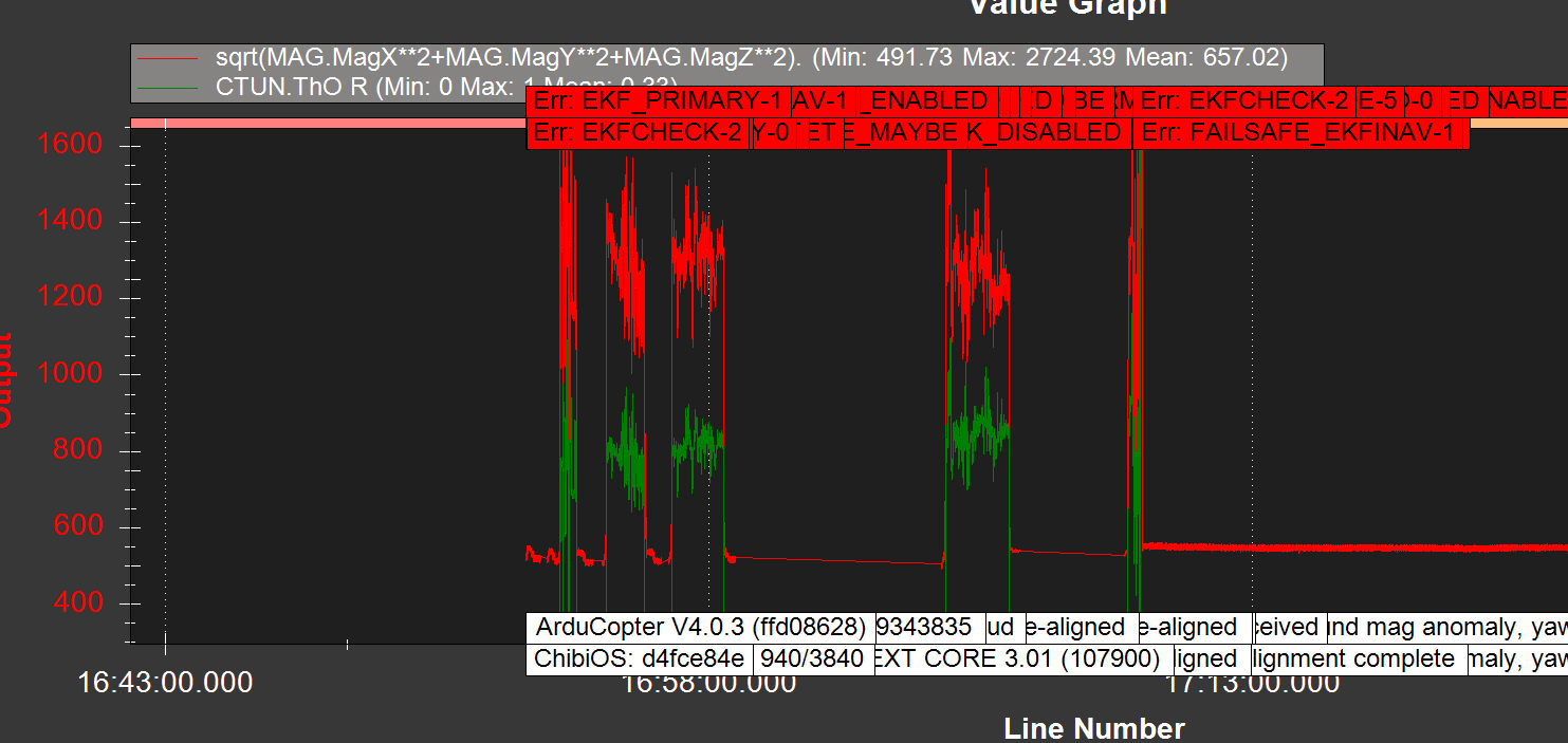
To help me better diagnose flight problems, I would like to be able to create graphs like the one above. I read the tutorial on using the graphical representation of parameters, but have not been able to create such a graph. Where can I find some instructions on making these complex plots? The other thing is the overlaps of the messages and errors. Can’t get much out of these because they overlap and can’t be read. How do I make any sense of this?
As you can see, I’m frustrated by having so much information available and not being able to use it to solve problems. As I get more familiar with this system I’m sure it will become clearer, but its a steep learning curve. Ain’t open source wonderful.
Thanks for the ongoing help. It’s nice to know there’s a lot of activity in this community.
I’m looking for a reason why I would need 2 compasses. If the one inside the controller is so affected by stray magnetic fields, why use it at all? Should I use only the external one? It sounds like its better to use the most reliable compass and eliminate the poor one.
Can anyone offer a rationale about the whole compass setup?
Don’t, that’s what I said and the common solution. Out of all the craft I have and have built I have used the internal compass on 2. A plane, where isolation is typically not a problem and one quad with a Pixracer mounted on the top plate, on a tall vibe mount and the battery is below the bottom plate. Only thing else on the top plate is the Rx. Those use cases work, others do not.
Today I connected the external compasses. There are two in the mRo NEO-M8N. I assigned one as the primary, but not sure if one is preferred over the other. Then I turned off the internal compass setting. The two compasses calibrated without any issues. I made 5 test flights in various modes including two AUTO missions. Everything went well. So for now I believe the issue is resolved. Further flights will tell.