After 4 or 5 days of messing with it over the last couple of weeks, I’ve worked a few things out now and thought I’d share them.
My setup is:
Hexa 800
Pixhawk 2.1 w/ Edison Base running Copter 3.5 RC3 (RC4 as of this posting)
Here GPS
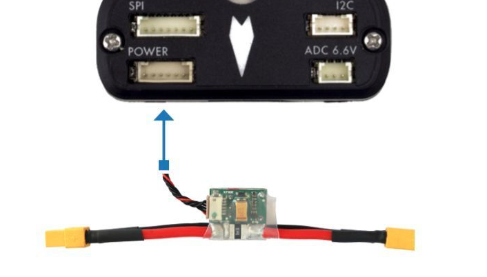
Mauch Power Module @ 6S (Using only 1 power supply)
Mauch HO Power Supply (Running Periferals, except PX4Flow)
Edison is installed
PX4Flow
Lightware SF11/C on I2C Powered Separately
1.3" Oled
Gimbal w/ Hero
380KV Motors with Xrotor 40A ESCs
Taranis X9D w/ X8R
FRSky FLVSS SBus Lipo
FRSky Telemetry Cable using Craft & Theory FlightDeck Hud on Taranis
Yes I have a lot of crap connected - I like to tinker. However, I’ve never even considered this to be a power issue. It’s what I do, so I make sure it’s right,
and I make certain I have plenty of spare capacity by putting all of my large loads onto a BEC and running as little as possible off of the FC.
There’s a real lack of info out there - or at least I had a hard time finding it - regarding connections, setup, etc.
Here’s the quick and dirty:
Telem 1 = Serial 1 (I have my Sik Radio installed on this port @ 115k baud)
Telem 2 = Serial 2 (if using Edison, set this to 921 baud and 1 for Mavlink - and do NOT connect anything to it)
GPS1 = Serial 3 & Safety Switch
GPS2 = Serial 4 & I2C (This is what my FlightDeck Telem Cable is connected to. I Hacked a DF13 into the serial portion and connected my Telem Cable that way - Set Serial 4 = 57k baud and 10 for FRSky Passthrough.
Edit:
Oxinarf has explained that right now, Copter is only looking at the I2C bus that is intergrated with the GPS1 port.
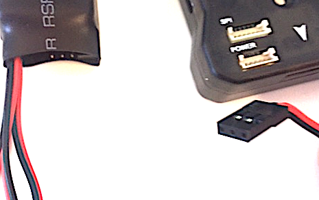
To correctly connect I2C devices you need to extend the wires for this I2C bus to your device, or as I did, splice a 4 pos cable and connector into these wires, and extend to I2C splitter. Here’s what I did, using the HERE GPS wires.
Note, you have to splice into the GPS cable to do this.
I spliced a 4pos I2C cable in using these wires on the HERE (do it nice - use solder and shrink tube and make sure your connections are done well, or find someone who can) Here connector is with the pins up - purple on right - I2C cable is pins up - red on right:
HERE GPS - Pin 1 Purple 5V = I2C cable Pin 1 (Red)
HERE GPS - Pin 4 Yellow I2C SCL = I2C cable Pin 3
HERE GPS - Pin 5 Orange I2C SDA = I2C cable Pin 2
HERE GPS - PIN 8 Black Gnd = I2C Cable Pin 4
Plug this 4 pin cable into your old I2C splitter, or if you used a new JST cable (like what comes with PH2.1) and want to use your new I2C splitter, it’s the same pinout - pins up - VCC on right.
If you aren’t using the HERE GPS I’d simply use the GPS1 cable that comes with the PH2.1 kit, and connect that cable’s I2C to your splitter, then take the GPS mag connection to the splitter.
The issue with this cable is that it isn’t really long enough to do what’s needed on the safety switch, serial connector or I2C connection. You’ll have to splice into it likely to make them longer.
Were it I, I’d splice your GPS cable into the serial of the PH2.1 cable, take the I2C of the PH2.1 Cable to the splitter, and then extend the GPS mag connector to the splitter.
I2C = Appears that only the GPS1 I2C bus currently works for devices, with Arducopter. Read above.
End Edit
USB = Speaker
I originally got everything connected and setup - and had a real time getting calibrated. The FC seemed buggy.
I couldn’t power it via USB or connect that way - without connecting the battery. All calibrations were slow to respond ro failed.
I managed to work through it, took it up and flew a bit on a Sunday seemed ok.
The next weekend, decided I’d go testing. Power copter up, hit safety switch, arm it, and it doesn’t spin up, and insantly disarms.
I narrowed this down to the Edison and once I removed it, the unit powered up via USB, and seemed to respond. Motors spun up.
I then noticed that my Telemetry was sketchy. It would simply lock the hud & the Pixhawk - not allowing me to connect to it.
I changed my log settings, to log less, turned on logging while disarmed, and changed the buffer size.
While this seemed to ease the telemetry issue a bit, it didn’t fix it and in fact, I started getting random strange errors.
This change on buffer size also kept EKF3 from loading - giving me a insufficient memory error.
So I changed the logging buffer from 40 - down to 20. This fixed the EKf3 error, but everything still seemed buggy.
So I turned off EKF3 all together. This fixed everything.
Telemetry worked, the laggy Hud updated and slow system performance went away.
I decided to reinstall the Edison just to see what would happen and whatdya know - I can boot it from just the PC USB connection, and connect to Mission Planner, all telemetry working, and the system is stable.
So, turns out the majority of my issues were due to EKF3. This makes my Telemetry Laggy on my other 2 Pixhawks, so it’s definitely taxing the system, but it must be even more so on the PH2.1.
Just loaded 3.5 RC4, did accel and compass calibrations and took her up…was super windy though but all seemed fine. Had to land it quick and tipped it though…log attached if anyone is interested.