i would like to put multiple CAN sensors (mateksys) and AP_periph modules on one CAN port of the pixhawk4.
They all have a 120Ohm resistor between CAN H &L. But i only need them on the end. Is there any knownledge on how well it still performs with all of them having the resistors? maximum distances/amount of can slaves?
How much current can the Pixhawk4 provide on the Can rail? Is it directly connected to the input voltages? how is power switched between the 2 Power inputs? Just a diode?
Is there any shematics or pcb layout available for the Pixhawk4? This would make it so much easier. I thought it was all open source hardware, but i can’t find anything…
I have read somewhere: overall bus length is much shorter than a wave can travel in one bit period (maximum bus length for 1 Mbps CAN is 40 meters);
As for power, you may not need if it is a low power device, otherwise you use UBEC and keep all the ground connected with FC
Looking at the Mateksys L431 Node, I dont see termination resistors, so you should be able to Daisy-Chain and put a JST=GH soldered resistor at end of line
Hi,
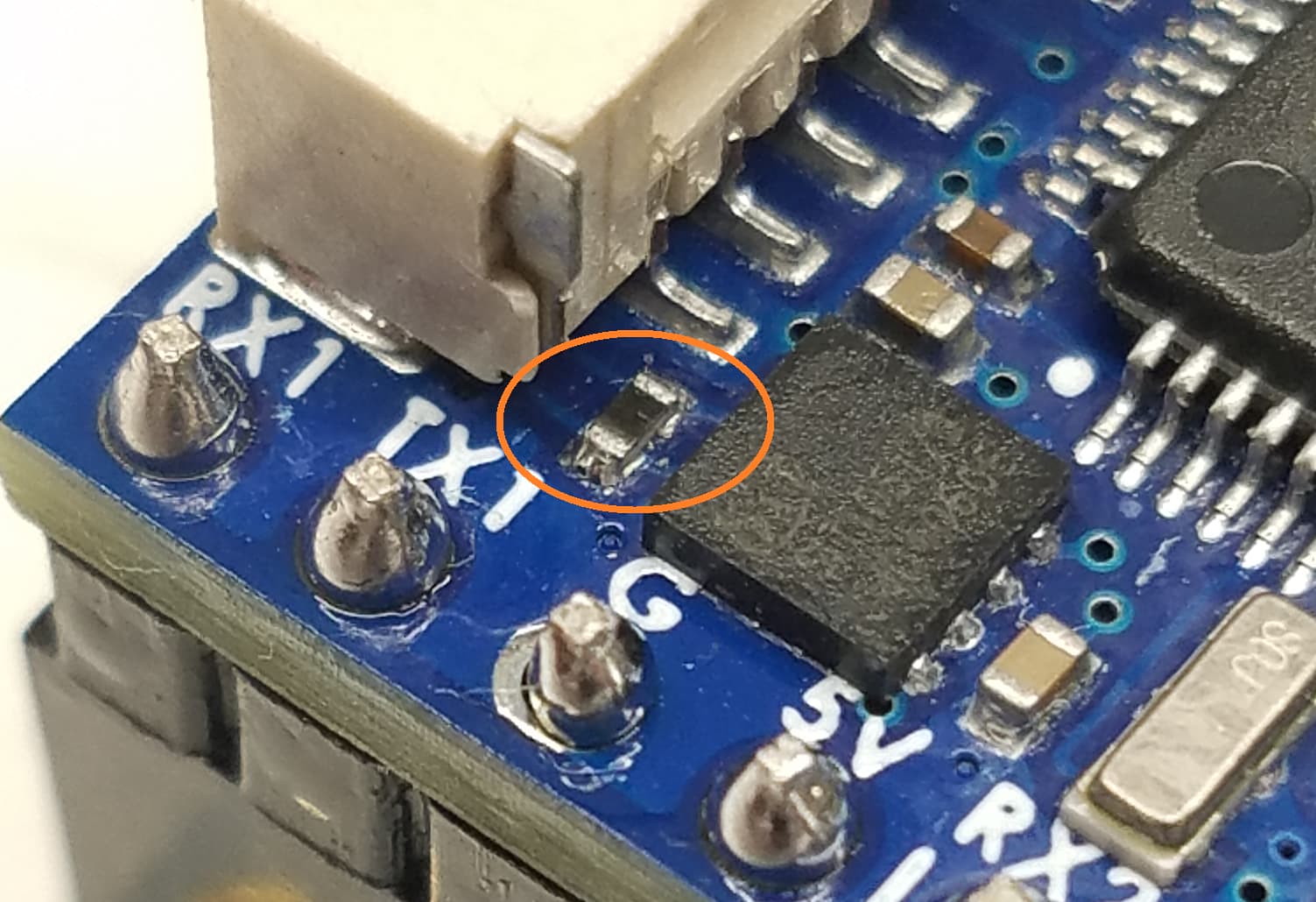
unfortunately the Mateksys L431 can node does have the 120 Ohms resistor.
combined with the other sensors i will have 5 times 120ohms in parallel on CAN1 and 3times 120Ohms on Can2.
Shematics of pixhawk 4 would be great to esily find the correct resistor in case we have to unsolder it.
Or might I suggest an electronic terminator that can be turned on/off via a parameter? Extra cost added i think would be worth it to many commercial users.
And easier to scale for those needing 5+ on a vehicle.
If the 120ohm is not required on this CAN node, we can remove it in next batch of production. but I think removing it is much easier than finding a 120ohm to solder it back for some users
I was thinking of a solder bridge easily accessible on back of board where you jump with solder to close the termination circuit with the 120 ohm already installed on board
Soldering the resistor is indeed too complicated considering the size of components
Bridging the Resistor would be 0Ohms, shorting CAN H and L.
A thin pcb trace serial to the resistor between H&L that could be cut with a knife would be a possibility.
I would not remove the resistor entirely. Too difficult to solder it on if needed. (Probably more often than not)
Since i have the equipment, i will just unsolder it for now and use the airspeed and GPS as endpoints. (keeping their resistors active)
→ Results in 3 instead of 2 120Ohms resistors.
to ensure reliability:
I will try it with all 5 resistors first, if that works it will be even bettwer with only 3.
Maybe i have a look at the Pixhawk 4 as well to make it exactly to the CAN Specs.
P.S.: Nice to have Mateksys so active in this group! Thanks for the nice products!
I just tried the can nodes. (no servos on output, just Oscilloscope till now)
After figuring out the different output numbering schemes in AP_Periph it looks quite promising.
One thing i would have loved is to select the Servox_funktion that will be transfered to the can bus, not only the already assigned servo outputs. Would make it much more flexible on complex aircraft.
Tested:
A)
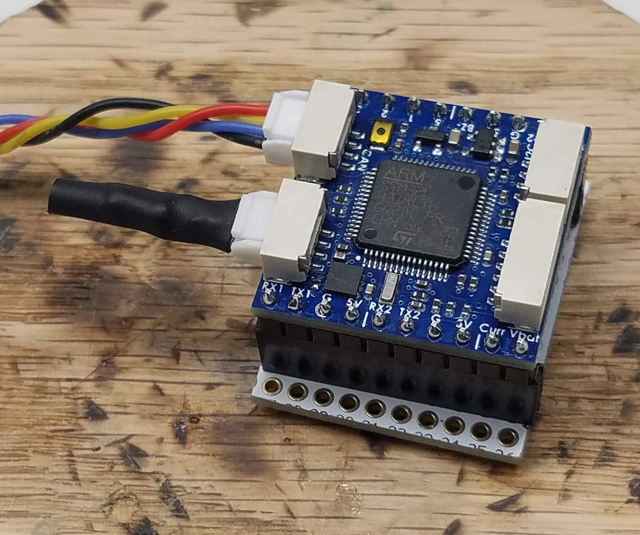
I tried 3 L431 CAN Nodes and one F405 CAN-GPS in series, attached to a pixhawk4. All with 120Ohms resistors.
Seems to work fine. Oscilloscope showed clean flanks on the Can H-L lines, but every 120Ohms resistor reduces the amplitude quite a lot.
With only 1 device it is ~2.3Vpp. With all the devices ~1.3Vpp.
Interestingly the Matek Can-GPS seems to input amplitudes almost double the amount.
→ Good for testing, but i will definitly unmount the cannode resistors and perhaps the pixhawk ones as well for flying. (resulting in 2 resistors at each end of the can bus.
B)
I tested bot CAN busses as well, transporting different servo signals over each bus.
CAN1: pixhawk - can node (servo pwm) - can node (servo pwm) - CAN-GPS
CAN2: pixhawk - can node (servo pwm) - CAN-Airspeed
Only problem: i was not able to update the airspeed sensor via slcan to the new firmware with correct name. Perhaps i have to do it over TTL.
unfortunately the bootloader on the F405 Matek airspeed sensor was not CAN enabled in the first production run. Since then we have a new firmware for the airspeed sensor which does have a CAN enabled bootloader, but for users with the old firmware the only thing you can do is update the bootloader to the new firmware using DFU over a UART.
The best would be if no CAN node has 120 ohm terminator permanently soldered. Simply include a JST-GH connector with 120 Ohm terminator that you can plug into end nodes.
Well, 2024 and we just experienced the dreaded can bus termination issue. Matek airspeed sensor, two nodes for gps have these resistors still on the board. and they are TINY! After removing all the 120ohm resistors i realised it will be impossible to re fit them as the soldering iron absorbed them! System now all good with them out and single termination at the end.