ArduRover 4.0 is installed on an Omnibus F4 V3 Pro.
Skid steering option has been set.
BRD_PWM_COUNT = 2
SERVO1_FUNCTION = 73 (Throttle Left)
SERVO2_FUNCTION = 74 (Throttle Right)
RELAY_PIN = 52
RELAY_PIN2 = 53
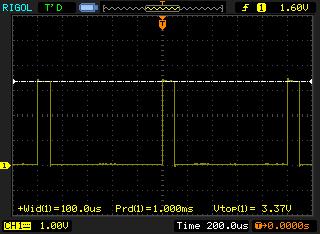
Preliminary testing of the motor setup included testing the PWM1 and PWM2 outputs with and oscilloscope. The following was identified.
At neutral or centre stick setting (including GCS Motor test), the minimum PWM period is 10% of the duty cycle, not 0%.
When full right stick setting (including GCS Motor test), the maximim PWM period is 90% of the duty cycle, not 100%
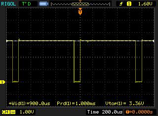
Similarly full left stick setting (including GCS motor test), the maximim PWM period is 90% of the duty cycle, not 100%

For all other stick positions, PWM outputs lie within the 10% to 90% duty cycle range.
The RELAY_PIN direction output behave as expected.
MAVLINK CH1 and CH3 messages are created using a USB Flight controller interface as a joystick, and has been calibrated.
I see no setting that can change this behaviour.
I have seen two ArduRover forum posts who commented on a similar behaviour about one year or more ago but with no responses.
Attached are the parameter settings saved from the Omnibus F4.
rover_4.0.param (28.0 KB)
Is this an expected behaviour?
If so, the motor would always want to turn as there is no zero volt point.