Makes sense!
Yes, I intended to use an ESP32.
Makes sense!
Yes, I intended to use an ESP32.
Ok, I added SBUS out of v 2.16.11 in Source/Experimental folder
Use this option in config.h
//=================================================================================================
//============================        F R S K Y    S E T T I N G S       ==========================
//=================================================================================================

#define Support_SBUS_Out  // Derive SBUS from F.Port and present it on a uart tx pin
A bunch of changes had the be made to switch UARTS around, so it needs testing. I ran out of time. 
EDIT: I coded for ESP32 variant 5 only for now. Added
    #define sbus_rxPin    99        // not used - don't care
    #define sbus_txPin    12        // Optional SBUS out pin - not 16
so I still need to select an unused pin for sbus_txPin on the other variants
Thank you so much for the quick response! I will try and give it a go very soon. My board is probably “variant 1,” but with your note regarding pin selection, I can probably make that work.
EDIT:
I must admit that I may have jumped the gun with this feature request, as the receivers I intend to use have SBus Out pins that will probably suffice. I will still try to test the experimental feature for you at some point soon, but it may not be necessary for my application.
Hey Eric,
I think my question was worded a bit oddly, I’m aware why mvBaud is a variable. I was actually wondering why mvBaud defined on line 57 states that it should be 57600 for dragonlink. And then on line 551 mvBaud is re-defined as 115200 for dragonlink. I was wondering if there was some sort of gotcha for mvBaud of 115200 with the dragonlink units. Sorry for the confusion.
Hey Kyle, your question was just fine. I would try 115200, and if you run into problems revert to 57600.
I have had some measure of success with the following configuration:
MAVLink ingestion seems to be working extremely well in all cases.
I’ve seen multiple notes in this thread regarding no need for inversion or 2-wire conversion for the Teensy, but this note remains in the Wiki:
While testing using a Teensy 3.2, my Archer M+ and Teensy did not work reliably in one-wire mode at 115200 b/s. I resorted to normal 2 wire (rx/tx cross over), with a two-wire to one-wire converter.
The config above is reasonably good with #define Send_status_Text_3_Times uncommented, but text messages are still garbled at times, and occasionally the telemetry link is simply lost (while RC/SBus still works fine).
I got slightly worse results with this conversion module connected to the Archer RS FPort out pin (the one labeled non-inverted) and FPort v2, and 2-wire serial on the Teensy.
FPort v1 seems even less reliable with or without the conversion module.
And all of the configurations performed worse on an ESP32, variant 1 (data seen intermittently and eventually stops altogether).
To summarize:
I have attempted to scour this thread for info, but 600+ posts are a lot to digest, and there is some conflicting info. What is the latest recommended configuration for reliable results? Should I be soldering up a 2-wire converter per your schematic much earlier in this topic? Is it possible that the R-XSR simply works better than the Archer series in this application?
Yuri_Rage: Thanks for the detailed feedback. I made the comment below after a particularly frustrating session trying the make the Teensy work on F.Port in OneWire mode at 115200 b/s. EDIT: There is no problem with S.Port at 57600 b/s. I was pushed for time and resorted to my homebrew half-duplex one-wire inverter/converter. The intention was to go back and try to understand the problem, but alas, as the proverb goes, the road to hell is paved with good intentions ![]()
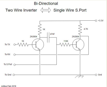
This circuit has worked well for me over the years, and usually works when all else fails:

EDIT2: Others, including Alex (yaapu) reported poor performance with FPort1, and I believe that was one of the reasons the protocol changed in F.Port2.
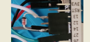
My experience is that the “conversion modules” with the RS232 board and reverse diode don’t work very well or don’t work at all. On the other hand, when signal inversion is not required, or has already been done by the mpu, a simple Schottky high-speed signal diode has generally worked well for me to achieve a “onewire” signal from a two-wire signal. I use a 1N5822. Here is an example on a Heltec board for use with S.Port. Pin 13=rx and pin 14=tx

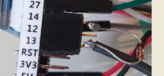
and here is an example for F.Port

Note that the diode is now reversed because the pulses are “normal” idle high, not reversed.
I’m surprised that your experience with the ESP32 and FrSky telemetry was poor. This is not generally the case, so I’m wondering if there is some other issue.
Finally, I guess you have seen this, but you should see packet loss reported on the monitor every 2 minutes.
//=================================================================================================
//                            O T H E R   U S E R   O P T I O N S
//=================================================================================================

#define Report_Packetloss   2         // Report S.Port & F.Port packet loss every n minutes
Yuri, I have been pondering over your post. Both ends of your HM30 will be transmitting relatively powerful RF. Have you taken care to shield and decouple the add-on bits like the Teensy and wiring in your relay setup?
Thanks again, Eric, for your quick response. Reported packet loss while the connection remains active is typically reported quite low (fractions of a percent).
I have not yet tried SPort - it requires a firmware change on the receiver that I was attempting to avoid. Glad to know that it may be a good solution.
I have a few signal diodes in stock, so it’d be easy to give that a try.
As for shielding - I really haven’t done anything there. Everything is just inside a makeshift enclosure that I cobbled together from some plastic retail packaging that was about the right size. Is there a particular method you’d recommend?
As for the ESP32, it’s possible that I did not have the correct one-wire connection and only tested properly with the conversion module that you mention as unreliable. I may revisit that.
Given the unreliability so far, I’m less motivated to try the SBus out feature, especially since I’ve found a solid means to avoid it.
I’m running into an issue where the esp32 is not outputting anything besides zero’s when monitoring the s.port output of esp32 which is on a dragonlink v3 unit.
I am baffled at this point. I have quadruple checked all settings and will list them below.
RSSI set correctly in missionplanner
Serial Baud (115200) in mission planner for data being sent to esp32
mvBaud variable (115200) in Mav2Pass
Dragonlink external connections set to GPIO 1 with a baud of 57600 (S.PORT)
Mission planner settings
SERIAL1_PROTOCOL = 2 (Mavlink 2)
SERIAL1_BAUD = 115 (115200)
BRD_SER1_RTSCTS = 1
SR1_EXT_STAT = 1
SR1_EXTRA1 = 5
SR1_EXTRA2 = 5
SR1_EXTRA3 = 1
SR1_PARAMS = 10
SR1_POSITION = 3
SR1_RAW_CTRL = 1
SR1_RAW_SENS = 1
SR1_RC_CHAN = 1
I have tried compiling various versions mav2pt with no luck on the serial output.
What is the best way to debug the esp32 on the dragonlink units? Do I need to use the additional pads on the pcb, or do I need to direct the debug print statements to a different serial output?
I’ve tried enabling #Mav_Debug_All & #Frs_Debug_All but am unable to get any legible debug strings while monitoring the serial output with my UART to USB adapter.
How have people debugged the esp32 on the dragonlink in the past? I need to get some serial output here so I can get a picture of whats going on, without it I am going in blind.
Anyones help is appreciated!
Hi Kyle, I’m away from home until May. Scott Pritchett did a lot of the work to intergrate ESP32 MAV2PT into Dragonlink. Maybe you can track Scott down on RC Groups.
Hey there Eric! i have flashed my heltec wifi kit with the 2.67.12, telemetry works, yaapu script can fetch it on the tandem x20. but Im having problem when i try to connect to the heltec via wifi. it says “couldnt get ip address”… any work around with this? thanks in advace!
i tried to flash the older 2.67.06 version, and here’s the logs:
Starting MavToPass version:2.67.06
Display support activated: Landscape
64x128 text_size=1 char_w_px=6 char_h_px=8 scr_h_ch=8 scr_w_ch=21
EEPROM initialised successfully
EEPROM settings version:2.67.6
EEPROM settings read and adopted
Relay Mode selected
Battery_mAh_Source = 3 - Define battery capacities in the LUA script
RSSI Automatic Select
Target Board is ESP32 / Variant is Heltec Wifi Kit 32
Mavlink Serial In
FrSky Serial Out
Mavlink WiFi Out - WiFi mode is AP
Protocol is UDP IP-Targeted
No Bluetooth options selected, BT support not compiled in
Mavlink serial on pins rx:27 and tx:17 baud:115200
Sensed serial port pin 13 is IDLE_HIGH, regular rx polarity
autoBaud - sensing pin 13
autoBaud: 57600 b/s
FrSky half-duplex on pins rx:13 and tx:14
For 1-wire applications a 2-wire to 1-wire converter or diode is required
WiFi mode set to WIFI_AP
AP_default_IP:192.168.4.1 AP_gateway:192.168.4.1 AP_mask:255.255.255.0
AP IP address: 192.168.4.1 SSID: DragonLink
Begin UDP using AP UDP object read port:14550 send port:14555
UDP for AP started, local 192.168.4.1 remote 192.168.4.255
Web support active on http://192.168.4.1
hb_count=1
hb_count=2
hb_count=3
Mavlink good!
SPort detected
FrPort read good!
Remote STA 1 connected to our AP
dhcps: send_offer>>udp_sendto result 0
dhcps: send_offer>>udp_sendto result 0
dhcps: send_offer>>udp_sendto result 0
dhcps: send_offer>>udp_sendto result 0
dhcps: send_offer>>udp_sendto result 0
A STA disconnected from our AP
==================
still, I cannot connect my mission planner to wifi. I confirm that mavlink setting is good, since when I connect the dragonlink tx via usb, i can connect my mission planner. Also, i confirm heltec wifi is working right, as i can receive yaapu telemetry on the radio… it’s just the wifi connectivity of the heltec that seems to have problem, often times, i cant connect to the heltec (set as AP), and when i got to connect to the wifi, i still cant connect mission planner/qgroundcontrol
what do these lines indicate?
Remote STA 1 connected to our AP
dhcps: send_offer>>udp_sendto result 0
dhcps: send_offer>>udp_sendto result 0
dhcps: send_offer>>udp_sendto result 0
dhcps: send_offer>>udp_sendto result 0
dhcps: send_offer>>udp_sendto result 0
just an update, i was able to connect to the heltec wifi AP. but still i cant connect either mission planner nor the qgroundcontrol. but yesterday, before I tried flashing the 2.67.12, it connects flawlessly (on 2.67.05). Currently i can access the webui. but i dont know why i cant connect the GCS
Hi Erwin, could you try switching the ports around. Use the web interface.
readPort - (default 14555) remote host (like MP and QGC) expects to send to this port
ok, i will try that ![]() earlier today i tried rolling back to 2.62.8, and it worked perfectly. then I tried flashing 2.67.5, i cant connect again… haha! i will still try to find out what’s going on. but first i will try your suggestion
earlier today i tried rolling back to 2.62.8, and it worked perfectly. then I tried flashing 2.67.5, i cant connect again… haha! i will still try to find out what’s going on. but first i will try your suggestion ![]() thanks!
thanks!
Hi Eric,
I am having a little issue on the MavToPass_v2.67.12 while running as a Relay mode on Heltec ESP32. Everything works but after 3~4 mins, Yaapu lua script running on QX7 radio starts showing no GPS even though I am receiving messages and other info on lua. While checking the GPS sensor on openTx remains working. Reboot of QX7 or (Heltec + Dragonlink) doesn’t not fix it. Only arduplane reboot corrects it but after few minutes, same thing.
I don’t get this phenomenon on Version 2.62.8. Any ideas? Thanks.
Hi ninja-zx11
Debugging this type of thing can be tricky. I think the best approach would be to try to get a tlog and then reproduce the issue. Is this possible in your setup there? I could also look at the change log to see if anything relevant was disturbed.
Ive been traveling and need a few days to get setup again.
Maybe you could use and extra serial port on the flight controller to pipe the telemetry to mission planner for the TLog.
Hello Eric,
No worries and please take your time.No rush at all🙂
Can I just use the USB port of the flight controller to connect to the Mission planner for generating tlog while I am waiting for the error to show up on my QX7? Thanks.