Ok just seen I need the mAh and Ah display not at all you could remove the from the script nicely and if yes how do I do that 
Hi,
you need to recompile the script to remove them, there no option in the config menu to hide mAh and/or Ah
Hi Mathew
My understanding is you want to convert Mavlink passthru telemetry out of the RFD (on the ground) to FrSky telemetry, then feed it into S.Port of the Tarnis. In this case you need to flash Ground Mode. The led should blink when the converter sees good Mavlink telemetry.
Use Mission Planer to set he Pixhawk serial port telemetry to the Mavlink 1 or 2 protocol at 57600 b/s.
The alternative is Relay Mode. Can I suggest you read up on that in the Wiki and decide if that is what you want Mathew
Ok, the example in the diagram was presented by one of the guys using ULRS, which sends telemtry at 19.2k b/s. In your case, susbstitue the RFD for the ULRS, and I believe you may use 57600 b/s.
So you want to use relay mode, the bottom option in the diagram. This differs fro ground mode in that you have a typical FrSky receiver, like an XSR, to relay the telemetry to the Tatanis. By doing this you avoid wires dangling out of the Taranis and leading to the RFD900 receiver. (I don’t have an RFD900 and my knowledge of that system is limited).
When the Mavlink 1 telemtry emerges from the ground RFD900 you convert it with the Teensy, and synchronise with the XSR receiver, which sends the data stream to the Taranis in native FrSky mode.
Note when you scan for sensors on the Taranis, two RSSIs should show up, one for the long RFD link, and one (unwanted) one for the short, XSR <–> Taranis link. I normall simply delete the unwanted one.
I might not be back on the net for a few days as I’m travelling.
Hi Eric, I’ve got this minor issue running a Teensy 3.2 With Alex’s LUA. I have both Tx and Rx connected to FC and #define Battery_mAh_Source 1, yet even after a few flights, battery cappacity is displayed as 0.00Ah. Everything else works.
Two copters, both sporting regular Pixhawk clones, one I’ve updated to 3.6.9, on the other I only had time to update the Teensy and Taranis, else running 3.5.7 iirc.
Hi Cornel
Battery_mAh_Source means battery capacity when full in mA hours. It can be read from the FC , as you have chosen, which means it was entered through Mission Planner battery setup.
Battery consumption, also in mAh is calculated as the integral sum of all the differential di/dt measurements during the flight, and this is deducted as you fly, from the reported battery capacity.
So, is your reported battery capacity when full correct, before you fly? Or is the consumption wrong during your flight so that the remaining capacity is reduced to zero too quickly?
Hi Eric.
Battery cappacity is correctly entered into the parameters list, and Mission Planner on the laptop shows correct percentages remaining.
It’s only on the RC, running Alex’s script that consumption is shown against a zero value. It doesn’t get the cappacity from the FC, so it displays like “3.71/0.00Ah”
I haven’t tried anything below 10.000 mAh tho’  so I can’t say where lies the problem. His satcount, for instance, displays 15+ for anything above, which for a regular NEO-M8N is OK, but with a ZED-F9 and 42 sats locked, that 15+ won’t do, anymore
Hi Cornel
Could you please send me a TLog.
Hi Eric.
Will a TLog from the laptop do ? Because I’m unfamiliar with logs stored on Taranis SD card.
Hi Cornel, yes, that’s what I need.
So I gave up on the ESP32 version of this a while back when I could not get my flavor of ESP32 working properly – Teensy is still going strong! I have now broken down and just ordered the same one that is referenced in the Git repo (with OLED and SD card). In the meantime I thought I would try again with my Wemos ESP32 Lolin. It is this one here.. The salient point is it is has OLED SDA/SCL on pins 5 and 4 of the ESP32.
The latest version of the code is now using the Adafruit library for the 1306 display. For the life of me I cannot see how to define the i2c pins used. That at least I had managed to get working in the previous version! We used to have:
#include “SSD1306Wire.h”
const uint8_t oledSDA = 5; // TTGO = 5; ESP Dev = 19; Other = 21;
const uint8_t oledSCL = 4; // TTGO = 4; ESP Dev = 18; Other = 22;
SSD1306Wire display(0x3c, oledSDA, oledSCL);
Now we have:
#include <Adafruit_SSD1306.h> //#define SSD1306_128_64 ///< DEPRECATED: old way to specify 128x64 screen
// Dev board default SDA = 21;
// Dev board default SCL = 22;
#define SCREEN_WIDTH 128 // OLED display width, in pixels
#define SCREEN_HEIGHT 64 // OLED display height, in pixels
// 8 rows of 21 characters
// Declaration for an SSD1306 display connected to I2C
#define OLED_RESET -1 // Reset pin # (or -1 if sharing Arduino reset pin)
Adafruit_SSD1306 display(SCREEN_WIDTH, SCREEN_HEIGHT, &Wire, OLED_RESET);
So how do I get my my I2C pins declared? I cannot see any such parameters and I even looked at the Git repository for this library. I am missing something.
And while I am at it I also find the connection from the Taranis SPort teleletry input and ESP32 SPort Telemetry output to be confusing. The FrSky telemetry output pin declarations are not with the rest of the setup but are in the FrskySportPassThru file.
frSerial.begin(frBaud, SERIAL_8N1, 12, 14); // rx=12 tx=14
I do not think I have to change these as I have 12 and 14 available. What does confuse me a little is we have defined a two wire connection here. Which one is connected to the Taranis SPort input pin? I know this is probably a fundamental misconception on my part but I have simply never grasped this with the ESP32 version of this project while it was never an issue with the Teensy version. Literally what pin do you connect to the Taranis telemtry input (bottom pin JR port)? Is it the TX 14? If we want bi-directional SPort telemetry then we would use a converter and use both pins?
Hope I can have the veil of confusion lifted! And thanks again for such a magnificent project.
(This is a cross post in the RCGroups forum. Not sure which one you check most.)
The latest version of the code is now using the Adafruit library for the 1306 display. For the life of me I cannot see how to define the i2c pins used
Marc, I found that the Adafruit SSD1306 library has a more readable font, and supports more vertical lines while remaining legible. It also supports SPI OLED displays, in addition to the I2C ones we currently use.
Your exasperation regarding pin definition is well founded. Lol. I can’t say I have put much effort into accommodating esp32 variants before, but you will be pleased to know I’ve just posted v2.28 with all the definitions in one place.
The Adafruit SSD1306 library picks up SDA and SCL from the Wire Class, and the default was 21 and 22. They are now defined explicitly in
   #if (Target_Board == 3)
     Wire.begin(SDA, SCL);
I do not think I have to change these as I have 12 and 14 available. What does confuse me a little is we have defined a two wire connection here. Which one is connected to the Taranis SPort input pin? Hope I can have the veil of confusion lifted!
Yeah, it can be a little tricky. In summary, it works like this:
In Air Mode and Relay Mode, the Mav2PT converter talks to a FrSky receiver (say XSR), and interleaves sensor packets into the sensor stream going down to the Horus/Taranis. In order to interleave a packet at exactly the right moment, it has to READ from the XSR and slot into a suitable gap in the stream. So the data read must get back into the Mav2PT.
However, in Ground Mode, when the Mav2PT talks to the Taranis/Horus and not a receiver like the XSR, it does not need to interleave packets. It therefore does not need to read anything, and therefore only Mav2PT txPin to Tarnis/Horus S.Port (rx) pin is sufficient. The OpenTX simply reads the sensor packets, and combines them with any sensor packets received from the receiver on the 'craft. So, in Ground Mode, one wire (plus ground of course) is always enough. This is true of the ESP32, the Teensy 3.x and the STM32 variants.
All FrSky telemetry is inverted with reference to mainstream serial telemetry. FrSky pulses rise up from (nominal) zero to 3.3v, whereas conventional serial pulses drop down from 3.3v. Furthermore, FrSky encode both rx and tx signals on the same wire. So this means when we talk to an XSR, or a Horus or Taranis, we need one bi-directional wire.
The Teensy 3.x has the capability of inverting and converting to bi-directional single wire internally. No inverter needed. No bi-directional converter needed.
The ESP32 variants have the capability of inverting the signal, but not converting to single wire (as far as I know at this point). So we must still do the two-wire to single-wire conversion when talking to an XSR, because we need to slot in our packets
The STM32F103C variants have no capability of inverting the signal, and no capability of converting to single wire. So we must invert the pulses and also do the two-wire to single-wire conversion when talking to an XSR, because we need to slot in our packets.
In Ground Mode, the STM32F103C variants must naturally still invert the signal with an external inverter because they are talking to a FrSky device.
Hope that lifts the veil. ![]()
1 Like
P.S. maybe I should include this explanation in the GitHub WiKi
It is like the blind man has had sight restored! Thank you for this explanation. I really appreciate it. You could copy and paste it into the git wiki.
Eric
I gave up on my current ESP32 efforts until the versions you recommend arrive. What really puzzled me was that I was able to compile and flash yet the SSID did not match the one I flashed. The oled was also confirming that Mavlink telemetry was being received regardless of whether it was being sent.
After flashing I am getting an error about missing headers in your patched ESP32 library. Yet it is compiling, seemingly.
One more question. I now cannot discover sensors on my Horus. I used to be able to. I have not updated my Teensy. Apparently I do not need to for Passthrough telemetry and my widgets are working fine. Just curious if this is normal behavior.
Marc, are you sure that the flash was successful.
Could you possibly show me a screen snip of the error message/s. Perhaps you could tick “verbose”, for compile and upload, in Preferences. Some libraries use pre-compiled C, but the exact .h or .dll is not obvious since I have compiled a lot of the esp-idf examples (outside of the Arduino IDE) on my development PC.
Unfortunately I don’t have a Wemos-Lolin with LED variant board, but I’ve made a folder of information from the link you posted. It looks like a pretty simple board. Remember, some boards don’t auto-flash after compiling. You have to hold down the boot button when the compile finishes, until you see the flash connect take place, then let go. You should then see the flash progress % reported. When completed, swiftly click Tools/Serial Monitor.
I re-installed my Arduino IDE from scratch and started with the latest versions of the Git repo as I want to solve my ESP32 issues. Been a while since I did a fresh install…
Here are the issues I found:
-
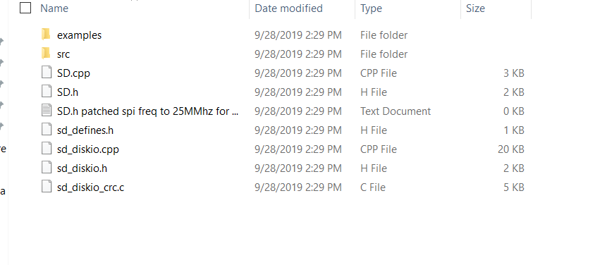
Arduino IDE did not like the My_Patched_ESP32_SD_Library files to be in the src subdirectory so I moved them and the compile error went away.
-
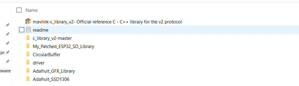
Not sure I have the Mavlink libraries correctly installed. I just used that link you provided and installed that collection of mavlink libraries from the zipped git download c_library_v2-master.
Still getting a load of compile errors. See attached. All relate to these librariescompile-error.txt (3.8 KB)
What am I missing here? Something silly as I did not have this issue before.
Thanks again,.
Marc
It looks like I’m having similar problems to what Marc’s seen. WiFi doesn’t configure and start correctly on the ESP32. Here’s the write-up I posted over on rcgroups:
Hello Folks,
I’ve been happily using this with Teensy in a couple of installations, along with an ESP8266. I wanted to get things reduced to a single board, so thought I’d try ESP32.
I’ve not had luck getting Wifi working on two different boards. The MavlinkToFrsky functionality is working fine. The Wifi functionality is not.
I’ve enabled the “Start_WiFi” define.
I’m using AP mode.
I’ve tried this on two completely different ESP32 boards with different pin maps. One which matches the kit here, plus the Heltec Wifi Kit 32. Both with displays (on different pins).
The display shows everything configured the way I set it in the config file. Including the SSID etc.
The board does start wifi, but the SSID which shows up is something like “ESP_NNNNNNN”. Different boards have different SSIDs. There is no password.
I can choose that network on the windows PC i’m using to test, but Mission Planner cannot connect. I’ve tried both UDP and TCP modes.
For the build environment, I’m using a clean install of arduino, with ESP32 board definitions and libraries installed through the library manager function of Arduino as shown here: https://robotzero.one/heltec-wifi-kit-32/
The sample app shown on that page runs fine and will display the wifi networks available when built and run.
The libraries from the MavlinkToFrsky project are copied into my libraries directory.
I’m using the latest 2.34 sources.
Should this be working? Any ideas what I’m doing wrong?
Thanks,
Scott
Edit: As a test, I tried not defining “Start_WiFi” and grounding P15 instead. Behavior was the same.
Edit2: I found that the SoftAP function of ESP_32 silently fails to start correctly if you provide a password of less than 8 characters. Changing that makes the AP start up right, and I can then connect to it, but I don’t get valid Mavlink data. I know the rest of the chain is working because Yaapu sees full valid telemetry, and my other ESP8266 setup works fine with all the rest of the equipment involved.
Edit3: On a hint from “Burgtree” on rcgroups, I changed the udp.BeginPacket() calls to use a hardwired broadcast address of “192.168.4.255” and that got udp mode basically working. The bad news is that it seems to not handle corrupted/dropped mavlink packets nearly as well as the ESP8266 code on the Ardupilot repo. Syncing parameters is MUCH slower using this code as compared to that.