Since our drone Current usage will be over 60A, we bought a Mauch HS-200 LV sensor for current measuring.
I use a matec UBEC (7V as output + an LM1048T-ADJ voltage stabilizer - 5.25V clean output as voltage source of Mauch.)
I connected it to our Cuav V5+. (cabled correctly the current and voltage pins)
I measure the following on mauch output
with standby load (590mA - 8.8mV 430mA - 8.2mV) pairs on current pin and 12.5V-1.27V 23.5-2.34V pairs on voltage pin.
(according if the source was a 4S or a better 6S battery).
The voltage is cleary good, the curent maybe distorted by some noise - or too small to have a good value.
But anyway neither in the qgroundcontrol nor in missionplanner I can’t see correct values for voltage. (if I set the devider for the 23.5V / I almost see the same value for the 12.5V.) furthermore I sent the telmetry data to taranis x9d with lua / here I can see the same.
but I’m not sure what to set for sensor type nor for the HW version.
I tried everything / possible the other/ 4.Cube or Pixhawk combination was the best.
So I’m stucked. Please help.
Thanks,
Syabolcs
Are you using the settings that come with the power module on the little bit of paper.
In first drop down of Autopilot your selecting what pins to use for the battery Input. You need to check for CUAV what that should be as follows
Set Monitor:Anglog Voltage and Current
Set Sensor:Other
Set APM Ver:CUAV v5 or Pixhawk4(for V5
Then for type you select other and then use the correction values provided.
The only thing that could be causing issue here is your using your own regulator and not the Mauch one. The values they provide are based on testing input on their own bec but as long as your the same voltage it should be fine.
I would go into the pram list then look at what pins are being assigned to what.
Hi, to be honest I haven’t found paper instruction, but I will ask my friend who arranged the order.
Anyway, now I did some succesful measures:
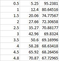
with the battery charger (discharge function) I could make an artificial load 0,5A,1A, 1,5A…5A and measured the mauch output. Above 2.5A it seems to be linear.
Also I set the CUAV v5 option as you have suggested and here I could see some close to the reality values (if I set correctly the 4A, I have seen 5.2A instead of 5A)
It is much more than yesterday was - where I haven’t seen any values.
This was the measued series, the first is the load(A) the 2nd is the Mauch output (mV), the last is the ratio
I don’t know how punctual the current is (internal measured value by the charger, the Voltage should be ok - 4 1/2digit multimeter.) the last row is questionable since I set 5A, just the maximum capability was the 4.8
The values that come with the MAUCH module are the voltage divider and amperes per volt inputs needed when setting up a power module.
These values are fine tuned for your specific module and are thus different between for each sensor. If you lost these values, I would recommend starting with the default values given on the documentation above and running your own tests to fine-tune the values.