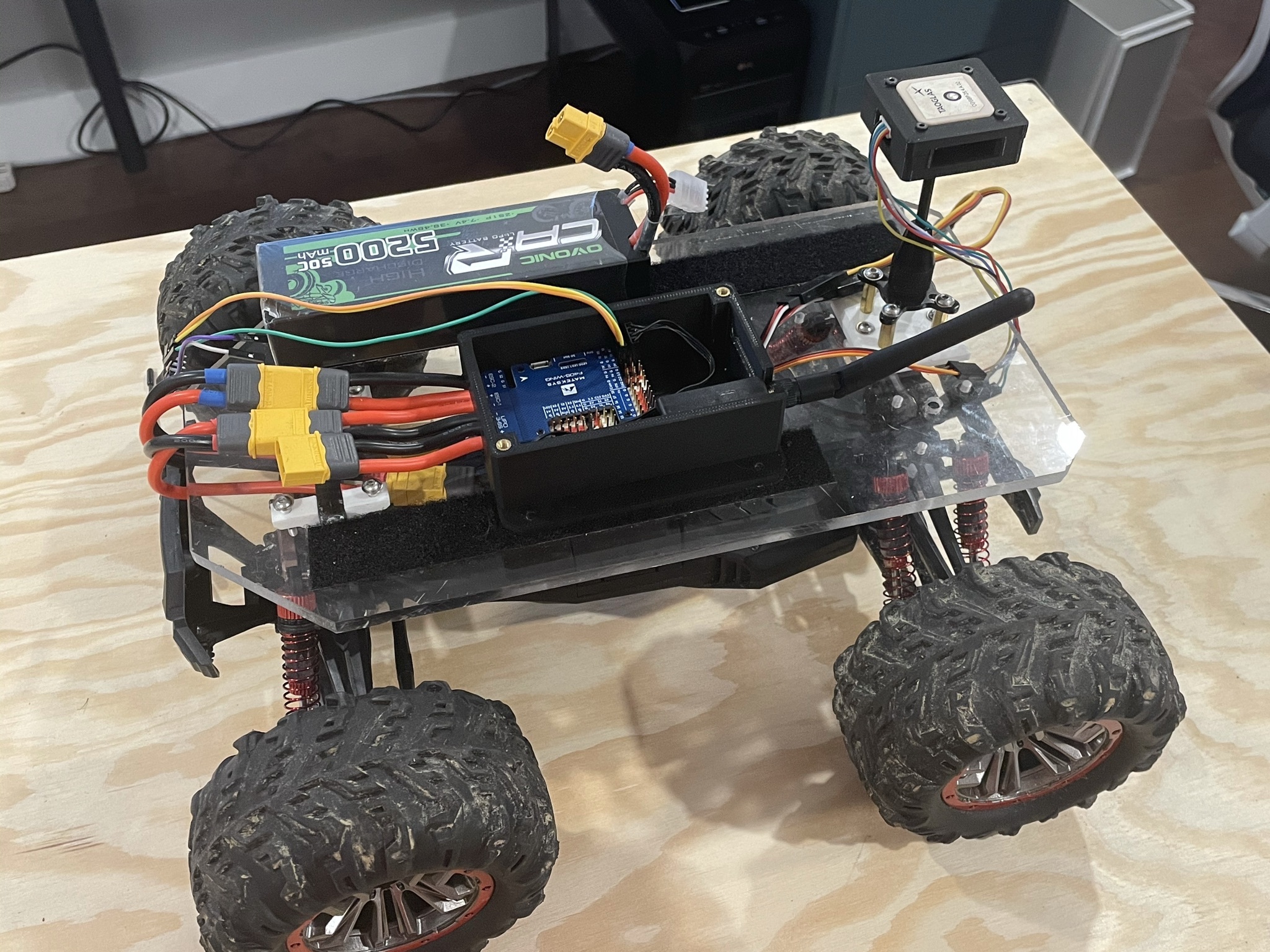
Hi! I’m running Rover 4.1 on a Matek F405-Wing for a ground rover project. I’m having an issue where the servo PWM outputs seem to randomly start outputting a faulty signal until I completely reset the servo channel configuration, at which point the output is fixed.
The series of events that happens to me:
On a fresh ArduRover 4.1 install on the F405-Wing, I wire servos to channels 3 and 4 on the flight controller.
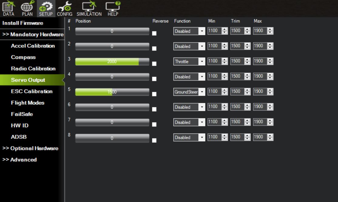
I configure the servo outputs for GroundSteering and Throttle. Everything works perfectly: RC input gets passed through in Manual mode, holds the center position in Hold, follows waypoints in Auto, etc.
Triggered by an unknown factor (Maybe a few power cycles), the servo outputs start outputting an invalid PWM output. This shows as 1) The servo not holding any position or 2) Servo driven into its endstop, sometimes breaking the servo.
Once the servo output channel is “broken”, it no longer works even between power cycles. I can plug in the servo to a previously unused channel which then works – So it’s not an issue with the value being sent from the autopilot.
If I “reset” the servo channel by setting its output to Disabled, power cycling, and changing its output back to the original setting, it works again! And repeat.
I’ve tried this on several F405-Wing flight controllers, tried downgrading Rover versions, isolating it to a testbed setup with only the flight controller, battery, and servos, and it still occurs.
I’m posting this here instead of an issue on the Git repository because I don’t think I have enough information to identify it as a bug. I’ve seen other similar issues like https://github.com/ArduPilot/ardupilot/pull/13814 - " Faulty PWM output after few flight controller restarts due to wrong IEP Timer configuration".
Does anyone have any experience with this, or recommendations for where to look/information to collect to narrow the issue down?
Thanks for the tips – I’ll get a scope on the servo outputs and post those results as soon as I can. I was able to reproduce it while logging, it seems like I can trigger it by unplugging the servo cable while being driven.
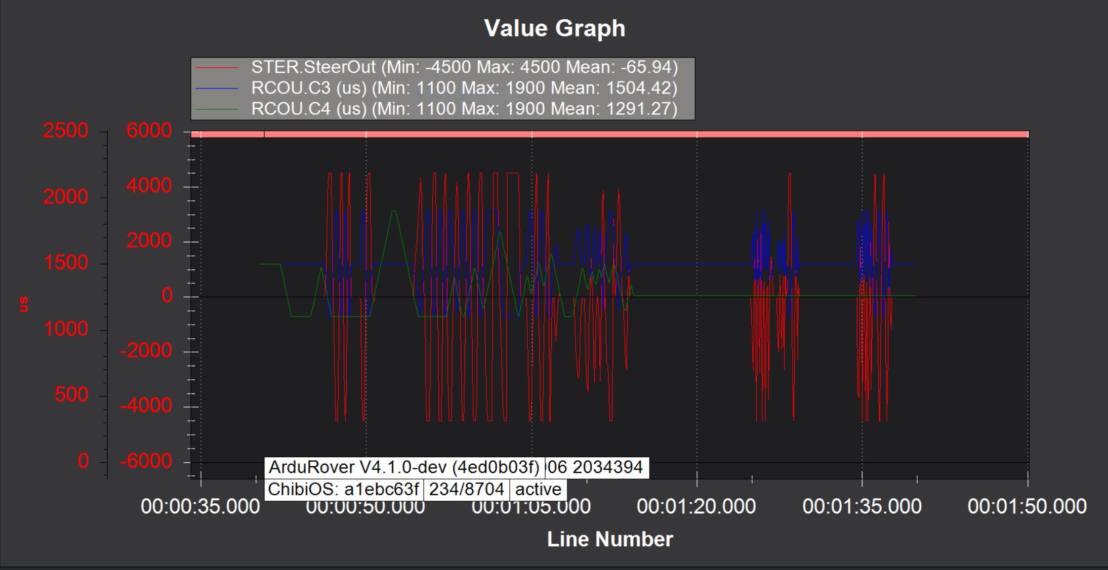
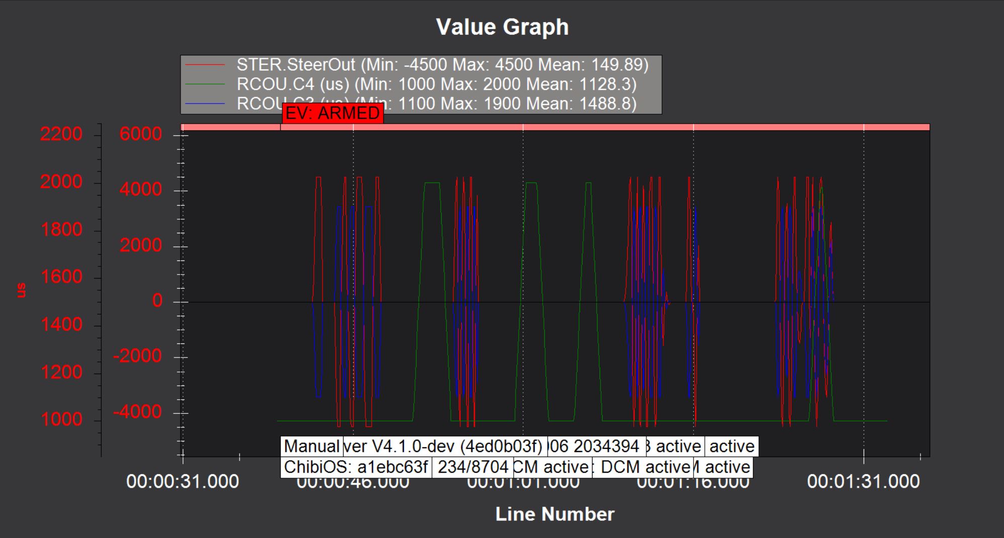
The charts/logs below show two tests. I have steering on channel 3 and throttle on channel 4. During the first test, the steering servo works properly. On the second test, after messing around with the cables and unplugging/replugging everything several times, the steering PWM signal on C3 is not working properly. Depending on which servo I use, the servo either interprets the bad PWM signal as nothing, maintaining its position, or interprets it as a value past the end stop, and runs to the end and breaks.
The chart still shows the same output values. I’ll have to get a scope on it to see what the signal actually looks like.
Just looked at the servo signals on the scope and it looks like at some point the output is being changed from a 50Hz servo output to some other protocol (Maybe DSHOT?) that I don’t recognize with a much higher frequency.
I tried keeping the throttle and steering in a separate output group, with throttle on channel 3 and steering on channel 5. I still get the same issue.
A few other things I notice:
The RCOut message on boot refers to the output groups like you mentioned: 7/18/2021 9:57:26 AM : RCOut: PWM:1-2 Brush:3-4 PWM:5-10
In this log message, what does Brush mean vs. PWM? Bipolar brushed controller?
After encountering the issue, the throttle output is outside of the min/max range configuration. Min/max values are still set to 1100-1900, but it changes to allow 1000-2000.
The other signal is Brushed signal, its just proper PWM with a 0 to 100% duty cycle rather than the not quite PWM we use for servos.
It seems to be working as expected, you have MOT_PWM_TYPE = 4 asking it to do that. The intermittentness I think is just that it takes a reboot to change the PWM type, so if you move the throttle output the PWM type change does not catch up until you reboot.
Set MOT_PWM_TYPE = 0 if you want a ‘normal’ servo out.
Oh! I see what you’re saying – so MOT_PWM_TYPE = 4 is outputting a normal PWM signal rather than the 20ms servo signal with a 1-2ms width. I see that now, on Brushed Motors — Rover documentation,
“Brushed BiPolar” motor drivers accept a duty cycle where 0% duty cycle means full speed in one direction, 100% duty cycle is full speed in the other direction and 50% duty cycle is stopped
I misread this as Brushed BiPolar being a normal servo signal, but it interprets 1500us as stopped.
For a brushed ESC that maps a servo signal 0% to full reverse, 50% to stopped, and 100% to full forwards, are there any settings I need to configure to tell the autopilot to map the throttle properly? After testing it seems like this is the default and I just have to setup the transmitter to send a throttle signal that centers for manual mode.
Thanks again for the support and explanation @iampete, everything works great now! I was definitely overthinking the whole thing and will read the docs more carefully next time