
"Ten thousand dollars?!?! It's just a piece of foam!"
I can't tell you how many times I've heard that over the past few years.
We will not debate the value of quality or workflow simplicity contained in that $10,000. What we will do is demonstrate how to take a $1,000 consumer fixed-wing drone out of the box and generate high resolution orthomosaics with a simple, repeatable workflow.
No time-consuming hardware integrations, just basic setup and an APM lobotomy for CHUCK. (He's the pilot.)
Tiny violins from here on out.

If you are starting with nothing, it will cost a little over $1800 for the three boxes that you need.
The finished hardware setup.
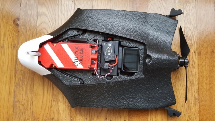
Required Components: Parrot Disco: $1,199 Hero5 Black: $390 Taranis w/ Rx: $237
Once you get the Disco and power it up for the first time, remember that it is just a WiFi access point running Linux. You can telnet and ftp to it like a normal network device.

When you're connected via WiFi, the Disco will be at 192.168.42.1

The goal here is to replace the brains of CHUCK with APM:Plane firmware. The primary advantage is increased flexibility in autonomous flight control and planning.
Let's take a look at the directory structure inside CHUCK.
 I used this guide to get Disco up and running with APM:plane.
In short, there are only three things you need to do to make Disco run the APM flight code. (double check your file permissions when you write these files!):
- 1) Upload the latest stable arduplane kernel to the /data/ftp/internal_000/APM directory. I used FTP to upload the file.
2) Create the start_ardupilot.sh script. I used vi to create mine in the same APM directory.
3) Modify the existing /etc/init.d/rcS_mode_default boot script to support the APM kernel.

Connect the Taranis receiver and GoPro. The receiver plugs in via the servo connector wire (see above image), and you'll need to dig out some foam to fit the Hero5. There is nothing to damage in this section of the plane so be careful, but don't worry about hitting anything.

We chose the Hero5 Black for three reasons:
- Self contained power system
- Internal geo-referencing of images
- Internal intervalometer
When considering other sensors, remember that losing any one of those features can significantly increase the complexity of the installation.
Once connected via Wifi, open a UDP connection in Mission Planner to verify correct operation of the vehicle.

The mavlink connection will open, and you will get live updates in mission planner.

Next you should compare your parameters with this known good parameter file.

Here’s how I normally do it:
- 1) In manual mode, check for normal control surface response in pitch and roll.
2) Switch to Fly-By-Wire A and check for proper surface corrections to roll and pitch attitude of the vehicle.
3) Still in Fly-By-Wire A mode, check for proper control surface output to transmitter input.
If you are not seeing proper control surface response, I would start by looking at the ELEVON_OUTPUT parameter. I use setting number 2. (Here's a great video from Mark Harrison if you need elevon help! https://www.youtube.com/watch?v=yvlCbs1NeC4)
When your control surfaces check out, you're ready to go for a maiden flight.
My typical maiden:
Everyone handles maiden flights differently, but here are a few tips for this Disco configuration with APM:
- 1) I use 3 modes; Manual, Fly-By-Wire A (FBWA) and Return-To-Launch (RTL).
2) Launch in FBWA mode at 3/4 throttle. Any of the normal wing launching methods will work.
3) Get "three mistakes high" and try manual mode. You will need to trim the vehicle.
4) Once those two modes are working, try RTL.
With a successful RTL, you're ready for an AUTO mission.
Create your polygon in Mission Planner, right click inside the polygon and go to AutoWP -> Survey Grid.

I used the Hero4 camera model, and increased the sidelap to 80% to generate my pattern.

The AUTO takeoff and landing works very well with this configuration. Do not be afraid to try it. Landing only requires two additional waypoints. LAND at 0 altitude where you want the plane to stop, and one waypoint before it about 200m away at 30m altitude.

Upload your mission to the vehicle, and then download it back to your ground-station to confirm accuracy.
When you're ready for your first AUTO flight, here are a few things to keep in mind:
- 1) Don't forget to turn on the camera! I used a 2 second timelapse, and it was way too many pictures. 700 images that were culled to 150 to produce the final orthomosaic. The GoPro WiFi was on and did not seem to affect my range checks. The voice activation is actually useful, "GoPro start a timelapse" was all it took to get going.
2) If you want telemetry throughout the flight, you'll need a WiFi adapter with an external antenna. Your laptop wifi antenna will not stay connected throughout the flight.
3) I keep the same three modes on the transmitter and put the vehicle into AUTO from the groundstation.
4) Once armed and in AUTO, you shake the vehicle to activate the motor and AUTO launch. Throw it into the wind and it will be on its way.
5) The vehicle is extremely well tuned. This mission was flown in 10-12mph winds on the ground.
6) It takes practice to nail AUTO landings. Be ready to take over control on long or short landings.
Ok, you've got your vehicle back after your successful mapping run. What next?
Remember that this is not a "smart" distance based capture. You need to go through your images, and cull the ones where the vehicle is turning, or has a lot of water in it, etc....
Then send it to your favorite orthomosaic tool!For this example, I used Pix4D Desktop. I used 100% default settings on the 3D Maps profile. Full processing took about 2 hours, and it came out great for this sensor!
 And a closer in view of the ortho.

We will see how long the airframe holds up; but Disco is a consumer product with readily available and inexpensive spare parts. You will not break the bank with, “Two is one and one is none.”
In summary, you don't need $10,000 to create large area, high spatial resolution maps with a fixed wing drone. A relatively small amount of money and basic maker skills can get you a cutting edge mapping platform from three boxes of consumer products.
Please let me know if anyone else tries this! Good luck!