Hi,
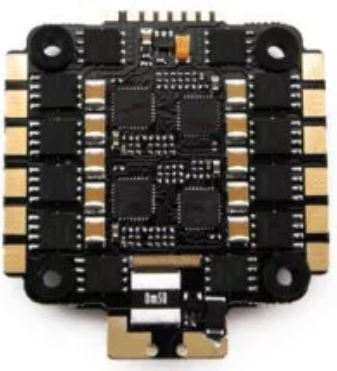
I have a Lumenier Elite 60A 4in1 ESC connected to a Cube Orange flight controller and I have an issue with the ESC telemetry. Everything in the Ardupilot configuration is setup correctly and I am getting motor rpm and esc temperature readings that seem correct, however, the voltage and current are wrong. The voltage stays at a little over 18V all the time no matter what voltage battery is connected and the current either says 0A or jumps randomly between 0A and ~6A. I have tried using battery monitors 1 and 2 by setting them to “BLHeli ESC” and setting the sensor to either “Other” or “Disabled.” All combinations result in the same issue.
Was wondering if anyone has come across an issue like this before to know if it is an Ardupilot issue or a software/hardware issue with the ESC. The ESC and Cube Orange are both brand new, as well as all the rest of the hardware on the quadcopter.
I’m not sure about your voltage problem but it’s possible current is not available from ESC telemetry but from the current pin only as total current equivalent analog voltage. I have an Aikon 4in1 that works that way. Do you have the ESC current pin connected to the Cube?
Edit: It’s configured similar to the Aikon I have. One large shunt resistor for total current. Your ESC shown.
That’s the confusing thing, I don’t have the analog current pin on the Cube connected, so the ESC telemetry is the only way the Cube is showing any current reading. Even when the motors are not turning the current jumps to random values. Maybe this could just be a software issue that occurs when the Cube doesn’t receive the response that it is expecting if the ESC doesn’t support current over telemetry?
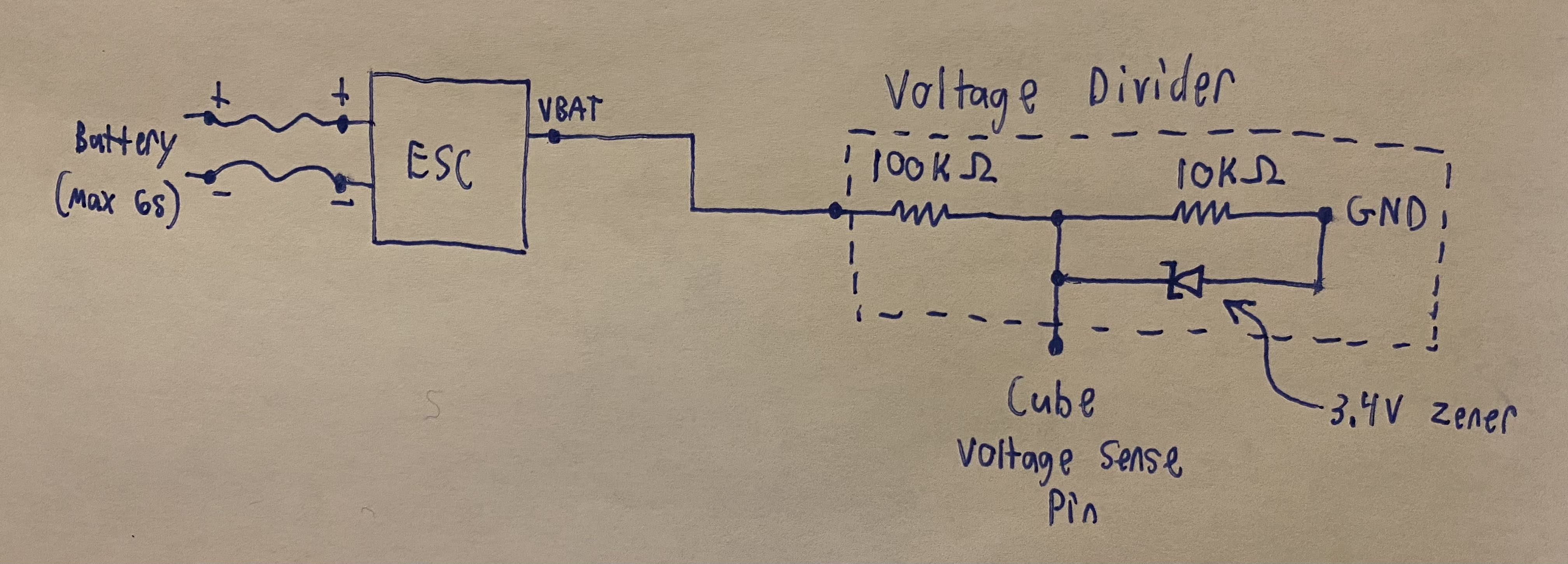
I verified just now that the actual pins on the ESC are working correctly for voltage and current. I connected the current pin directly to the analog current pin on the Cube and made a voltage divider for the VBAT pin so that the Cube can read 0-3.3V on its analog voltage pin. Both seem to work correctly, double checked the readings from the Cube with a multimeter.
With those resistor values it can theoretically measure up to 36.3V without exceeding the 3.3V input limit of the Cube voltage sense pin. I will only be using a 6S battery at most, but those resistor values are common so I just went with those since it gives some headroom. I didn’t use one while testing, but I’ll probably add a 3.4V zener diode like in the schematic to protect the Cube from voltage spikes.