I have a general question thats bugging me for a while. Basically, as we all know in large wingspan aircrafts the wires run long.
for context, i have a large wingspan VTOL. each side of wing is split into 3 parts. At the far end of the wing is our CAN based Matek ASPD sensor. Now the supplied cable is just 20cm. But my pixhawk is all the way inside the fuselage which is 3 m+ (hence the multiple splits in the wing) from the ARSPD sensor. Can anyone help me understand how can i extend the wire while going through 3 sets of D-sub connectors along the way to reach the AP. I have the understanding that i require Shielded twisted pairs (2 pairs) But, what i am not sure about is how to work with the shielding on the wires. Especially with all the breaks alongs the way.
Just FYI, I have similar issue for Servo PWM signals for which i want to employ the same STP.
I do not understand your issue. Please rephrase the question.
CAN has A,B and GND. All you need is to connect them. What GND issues/questions do you have?
the matek DLVR-ASPD sensor i am using have 4 wire CANBUS sensor (PWR,A,B,GND). I have acquired a Shielded wire with 2 twisted pairs in it. I will use 1 TP for signal A&B and use another TP for PWR and GND.
Now as i said in the top post. The distance from sensor to FC is 3m+ with 3 breaks in the middle. Each break has a Male-Female Dsub connector pair. So, my issue is how do I work on the shield aspect of it.
OK, now we are getting somewhere. Connect shield to GND at the FC side. Otherwise keep GND and shield separated.
Dsub9 has 9 pins. Use 5 of them them for:
Yes. So i know That ideally, only one side of the wire shield should be grounded not both. However, I have dealing with multiple breaks. So how to i deal with intermediaries?
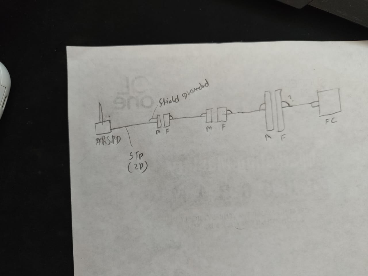
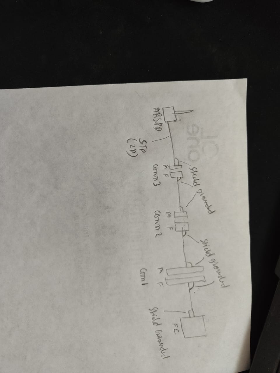
Please have a look at this rough paper sketch and tell me if this makes sense to you and right.
As you can see my current understanding is to connect shield to FC GND rail. and on the other end connect shield to Conn1 F pin. then for intermediates- for Conn1 M to Conn 2 F, Conn2 M to Conn3 F Each connected piece will have a shield pin connected too. Finally on for wire segment between Conn3 M to sensor- only the shield on conn3M must be conected not on the Sensor side.
Let me know if this is right or i am completely wrong AF.
Also, is the understanding right when we say that each connector (male or female) will have a pin that will be soldered with the shield. Just like i am depicting in the diagram?