Here’s a log with strange voltage behaviour, in fact I had to change the voltage scaling to get the arducopter to arm and that didnt work, so I had to disable voltage failsafe, so the CUR/Volt is not technically correct but out by a couple of volts. Although there’s no Failsafe condition here, I believe the behaviour is related.
In this log where you can see:
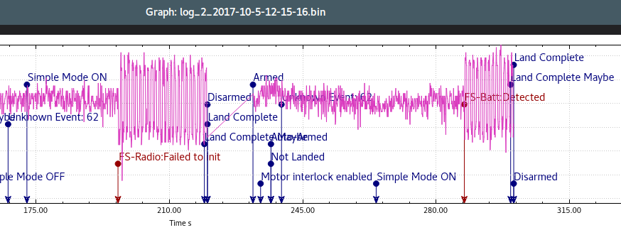
55 secs POWR/Vcc goes crazy on arming
During flight voltages are sort of normal, except that POWR/Vcc mirrors that of CUR/Volt
Land and disarm at about 280 secs, POWR/Vcc and CUR/Volt return to “normal” and fluctuations stop and measuements look believable for the first time
302 secs, arm and POWR/Vcc goes crazy again then goes back to mirroring the fluctuations of CUR/Volt
Vcc continues to follow Volt for the rest of the flight until Land and Disarm - normally Vcc would be fairly independant of Volt
I’ll check some old logs for more examples of the Failsafe condition.
I’ve only got Holibro PDB but it seems rock-steady when measured with a DVM. I cant fault it so far, and yet at the same time (on the bench) the Pixfalcon/Arducopter is reporting variation in Vcc and battery voltage.
I might need to enable logging while disarmed to gather more info.
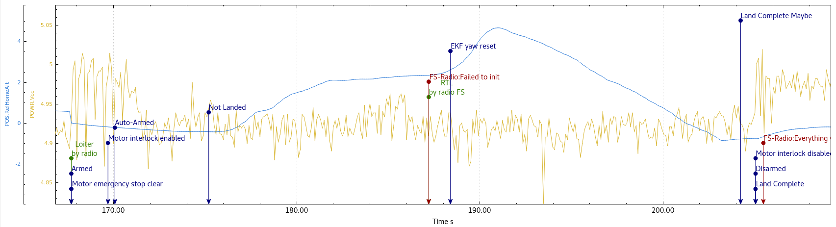
Here’s a good demonstration of the FailSafe conditions and Vcc. In the log file CUR/Volt varies in exactly the same way as the POWR/Vcc shown in the screenshot, and returns to “normal” expected voltage readings outside the FailSafe conditions.
You can see that the first FailSafe event is “Radio” as we were testing the FailSafe operation and RTL behaviour before unleashing the quadcopter upon the world.
Maybe if I confine this thread to the POWR/Vcc and CUR/Volt readings that vary after FailSafe, that would help.
I’ll pursue the general voltage variations separately, or under another thread if I must.
Thanks in advance to those the look at this thread and try to help.
I have now fixed my other variable voltage issues with the Pixfalcon connectors and will do test flights over the next few days to gather new logs regarding the strange voltage readings seen at FailSafe events.
Any ideas?
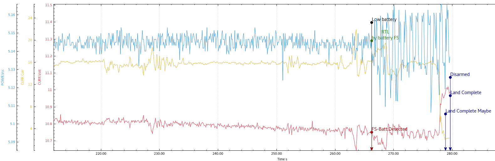
To me it looks like a logging issue, rather than the voltage actually varying. You can see when the craft lands and battery voltage recovers as current goes down, the Vcc is still going crazy.
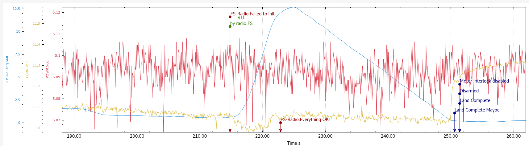
Here’s a new log with Vcc and Volt “humming” along nicely as expected, then I initiate fail-safe via throttle cut, then later by RC-Loss (now both set correctly and behaving as expected).
After fail-safe is triggered the Vcc and (to a lesser extent) Volt go crazy with cyclic regular variations. The variations go away and behaviour returns to normal only after landing is completed and flight mode is changed and the copter can be rearmed to clear the FS condition.
This screenshot shows just a portion of the log file.
Sorry to be annoying, is anyone going to look into this?
Not sure if it’s a Arducopter firmware issue or a hardware issue, but I’m sure it’d be worth knowing if we should be concerned about it or not.
Even if there was a definitive statement like “don’t worry about it, we investigated this before and it’s caused because of XYZ and cant possibly affect flight” then that’d be great.
I’m not up to contributing to the code myself, but I can sure run more tests and gather logs if needed.
So the board voltage is going up and down by about 0.15 volts (or 3%). It’s noticeable in the logs but it’s not a huge variation really - at least not large enough to cause issues that you’ll notice in flight.
I suspect that the small variations showing up in the battery voltage are actually caused by this variation in the board voltage because the way it measures the battery voltage is by comparing it with the board voltage.
Michael DB told me he suspects it’s the buzzer and that seems very likely to me. The wave in the voltage seems to be at about 1hz and very regular so I suspect if you disconnect the buzzer the wave will disappear.
I’m surprised the buzzer could cause this voltage change. It could be board specific - for example the voltage regulator could be larger/smaller on different boards. I’ll try and test a couple of my boards here (Pixhawk1, Cube, mostly) to see if they exhibit a similar problem.
I used to have the buzzer disabled, and I’m pretty sure the same peculiar voltage readings showed up in the logs.
I’ll do a test with the buzzer disabled and post a new log in a couple of days time. During failsafe condition, the Pixfalcon makes repetitive tones, not a continuous beep, but a new log will show if the tones are having an effect.
I just looked in the log again and the variations are happening from boot time right up until arming (actually to motor interlock) - at times there would be noises from the onboard buzzer but not continuous for the whole 50+ seconds.
I completely understand what you say about the CURR/V varying due to using Vcc as a reference, that makes sense.
It’s not so much the voltage swing of Vcc that I was worried about, since it stays within limits, but the fact that it seems to happen around specific events and was wondering if it’s a cause for concern or indicating some other issue.
OK, if it’s not the buzzer then it is probably the LED. This can also be disabled by setting NTF_LED_BRIGHT to 0.
@WickedShell, here’s why I think the package voltage is also changing:
I suspect that the small variations showing up in the battery voltage are actually caused by this variation in the board voltage because the way it measures the battery voltage is by comparing it with the board voltage.
Here’s 2 logs from one session. Fail-Safes are initiated by throttle cut.
The first log is waiting for arming conditions, flying to ensure everything works normally, Fail-safe and land to set a baseline. Then I disable buzzer setting and reboot for some strange reason, even though these settings take effect immediately.
The second log is arming and flying to fail-safe with Buzzer disabled, disabling LED and flying to fail-safe again.
If I’m looking at this correctly, it seems to me like disabling the LED has the most positive effect on the Vcc - which is unfortunate because we can easily disable the buzzer and live without it, but we NEED the LED to confirm take-off readiness since I don’t have telemetry radios to a ground station.
I’ll wait to hear others conclusions - but I think I’ll be leaving the buzzer and LED enabled unless it actually causes an issue.
To me it still looks a bit like a programmatic issue or possibly related to A/D conversion, since the variations in Vcc don’t match up with the LED or Buzzer activity precisely, and are only present prior to arming and during fail-safe - normal flight is OK.
Alright, I feel I’m getting close to pin-pointing if this a real thing or not…
Here’s a log and screenshot with Buzzer Disabled and LED Low.
The LED Low setting doesn’t seem to be visually any different to high or medium, but anyway I’ll leave it at low.
This indicates there’s no issues with Vcc related to pre-arm, fail-safe or disarmed, with the Buzzer Disabled.
Before I rejoice, I’ll do another flight with Buzzer Enabled to see if the issue returns:
obviously if the buzzer is causing the Vcc variations then at least we know what it is and how to disable the buzzer.
If the problem doesn’t return with the buzzer, then it must have been something else that’s changed…
Alright, what’s going on? I officially don’t get it.
Just did a test flight with Buzzer enabled and LED low, no sign of Vcc variations during pre-arm or fail-safe.
No other wiring or anything changed, firmware and all still the same…
Correction: some time back when removing the Pixfalcon power connector and joining wires directly to the board, I added an external connector (balance plug style) and a 22uF tantalum capacitor at the new connector - possibly this gives the 5vdc (Vcc) enough guts to maintain it’s level while LED and Buzzer are both in use, such as in fail-safe conditions.
Edit: I only added the cap to the new power wiring in the last week or so, there’s still logs in this discussion that display the symptoms even after I had replaced the Pixfalcon power connector (since this post on 22/09/17 Logged voltage varies after failsafe).
Maybe the combination of buzzer enabled and LED high would cause the variations? Maybe another test flight coming up.
So for now I’ll be leaving buzzer enabled and LED on low, since the buzzer is very handy and the LED is essential.
Probably should put this thing to bed! I can no longer correlate the variations in Vcc with repeatable events. Maybe it’s because I removed the Pixfalcon power connector and soldered wires direct to the board and added a capacitor across +5v and 0v. Maybe it’s times of the day or phases of the moon… No other wiring changes though.
Here’s a graph from today that seems to show Vcc variations only AFTER landing from fail-safe, and not during failsafe or before arming like in previous logs (before I did any wiring changes). Battery voltage and current didnt have any unexpected variations. Conditions were windy.
If anyone’s interested enough, I’ll upload the actual log.
If you see variation in Vcc related to Fail-Safe events or while not armed, test with buzzer disabled and LED disabled individually.
If the variations go away, decide how much you need the LED or buzzer.
Even though the variations might not be going low enough to cause a brownout or other issues, it’s probably a sign you’ve got problems with the power connectors, wiring or the power brick/PDB.
I’d suggest any strange variations in Vcc should warrant investigation of your power supply and connectors anyway.
The Pixfalcon has JST-SH connectors (I think) and they’re very tiny, might be a reliability issue there. I’ve pretty much eliminated the variations by soldering power wiring direct to the Pixfalcon board and adding a polarised cap across the supply. Your own remedy may be much simpler than mine depending on your flight controller and connectors.
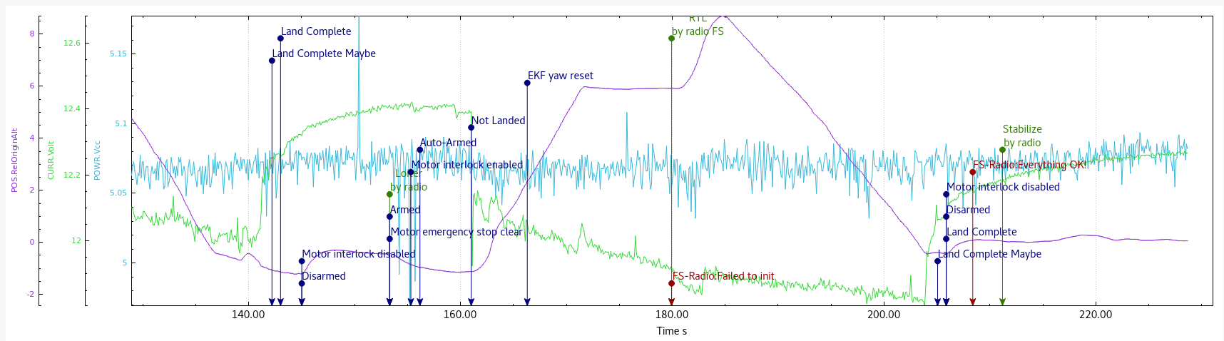
This pic from earlier in the thread demonstrates the problem, so you don’t have to read all the way through the thread: