Maybe. Never tried CRSF on a non DMA port.
Alternatively I could try moving the GPS from serial 4 to 3
I would try that 1st.
1 Like
Still see the “PreArm: FETtec: 4 of 4 ESCs are not running” error after swapping ESC telemetry to the Serial4 DMA port. (Btw GPS works fine running on serial3)
I tried setting Serial4_protocol to 38 (FETtex_OneWire) and 16 (esc telemetry - with this option I get Prearm: no Fettec UART error) but still no luck. When set to 16 I see esc telemetry displayed so the data is definitely coming through. I’m also able to run all motors when doing the motor test.
Anything else I might be missing? If not, maybe just ignore the message (perhaps it’s just a warning to tell you that the motors are not armed)?
Maybe I could be missing this - though I not sure which Tx it’s refering to (prob the reciever?)
The signal-pins S1, S2, S3, S4 from the ESC are used to receive the commands from the flight-controller, so the serial TX from the flight-controller must be connected to every signal-input in parallel.
No. As per the doc.
so the serial TX from the flight-controller must be connected to every signal-input in parallel.
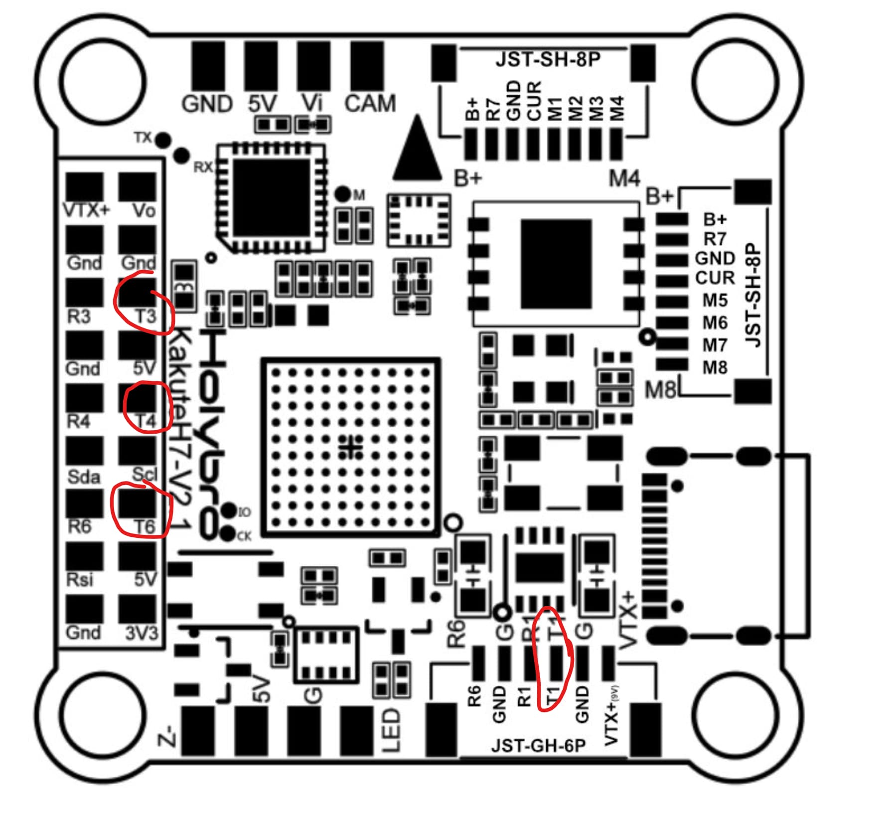
You are not connecting to FC TX pins in parallel you are connecting the signal pins on the ESC in parallel to one (1) Tx on the FC.
As I said I don’t have this hardware to test but the docs seem pretty clear to me.
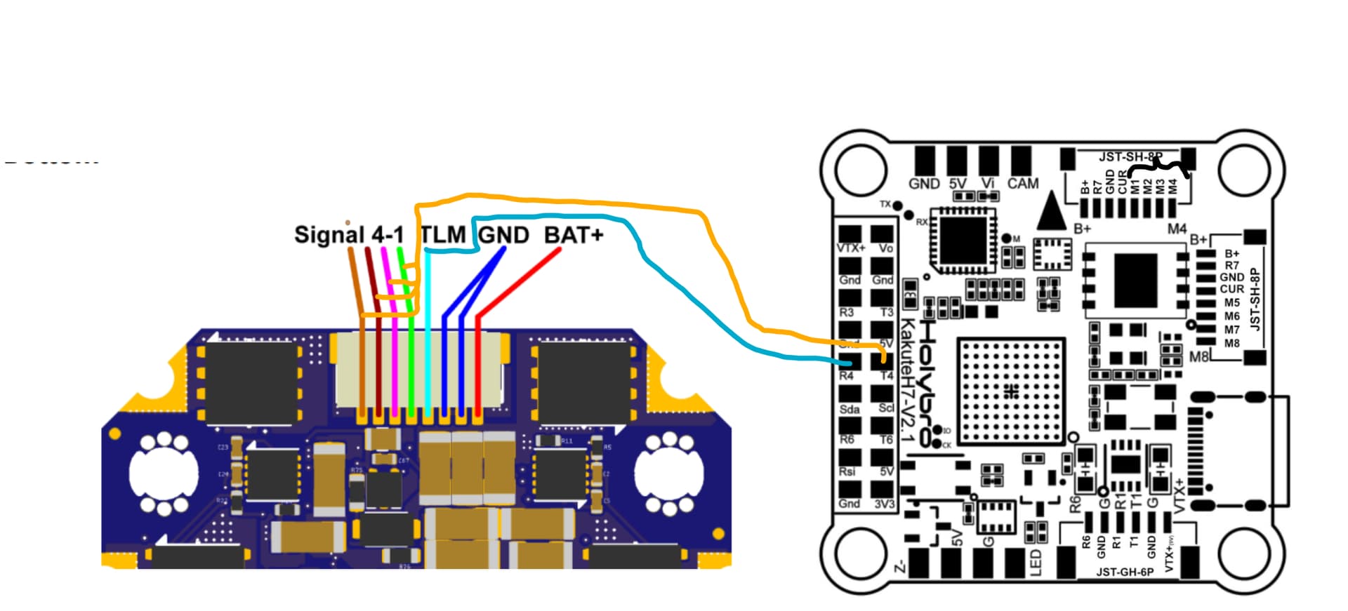
Connect the TLM output from the ESC to the Rx pin of the serial port you have chosen.
Connect the signal pins on the ESC (S1-S4) in parallel (tie them together) to the Tx pin of the same serial port.
I’ll let someone else chime in here that has actual experience with these.
1 Like
Yes I believe that is what Dave means
Yes
NO!
A primary advantage of these is the One-Wire serial connection. It carries all ESC signal data.
You won’t smoke anything at the signal level but I suggest you carefully read the docs to understand how it works.
3 Likes
Thank you all for the help - finally got it working with your suggested change!
Successfully cleared the pre-arm warning after doing this.
Looks like the OSD is displaying the incorrect battery voltage and current. Mission planner displays the correct voltage but incorrect current (127A for unarmed quad). The current displayed for individual ESCs looks right. Looks like I need a way to set this to the summed up currents of each esc.
I’ve tried setting batt_monitor to 4 (analog) and 9 (esc), but still no luck.
…
Start a new thread.
1 Like