John Easton's battle with 'Wobbly Path' - [NOT SOLVED]

That is a VERY valid point mroberts, the craft is not capable of making that turn to the next lane!

Unfortunately my sidescan mosaics have to be max 25m apart, which is half my turning circle, so I need to create two missions for each area, that is going to be tricky with ‘Corridor’ planning.

Thank for pointing that out.

Regards
John

John,

I want to help here and I’ve been noticing that you’ve been having trouble. I fly planes mostly, but I looked at your recent logs and I have some ideas. The first important concept is that there are steering and navigation controllers. Without getting good steering, it won’t matter what your navigation controller demands because your boat won’t be able to follow it. I think we’re mainly concerned with the steering control here.

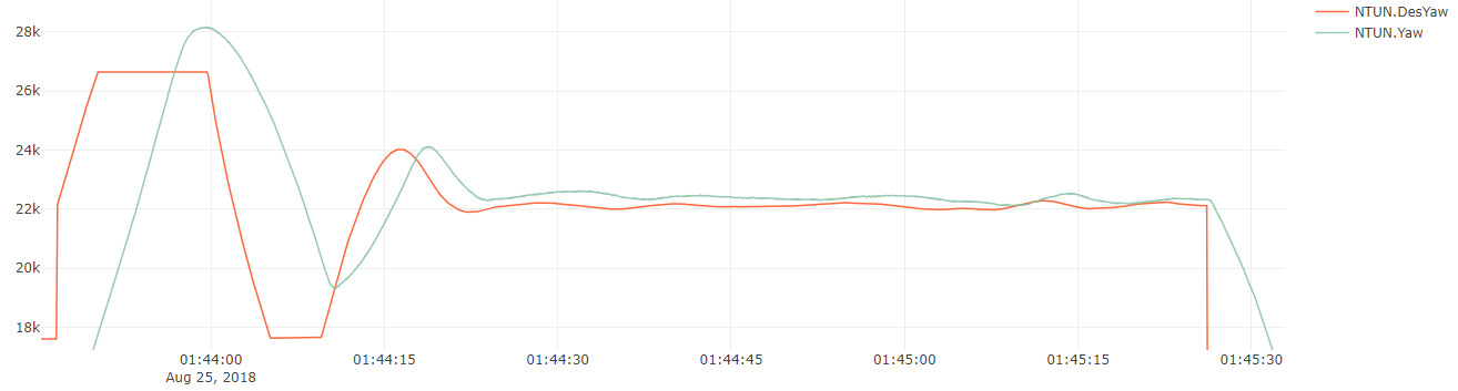
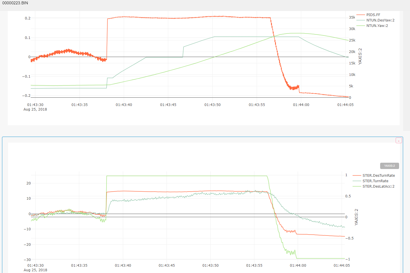
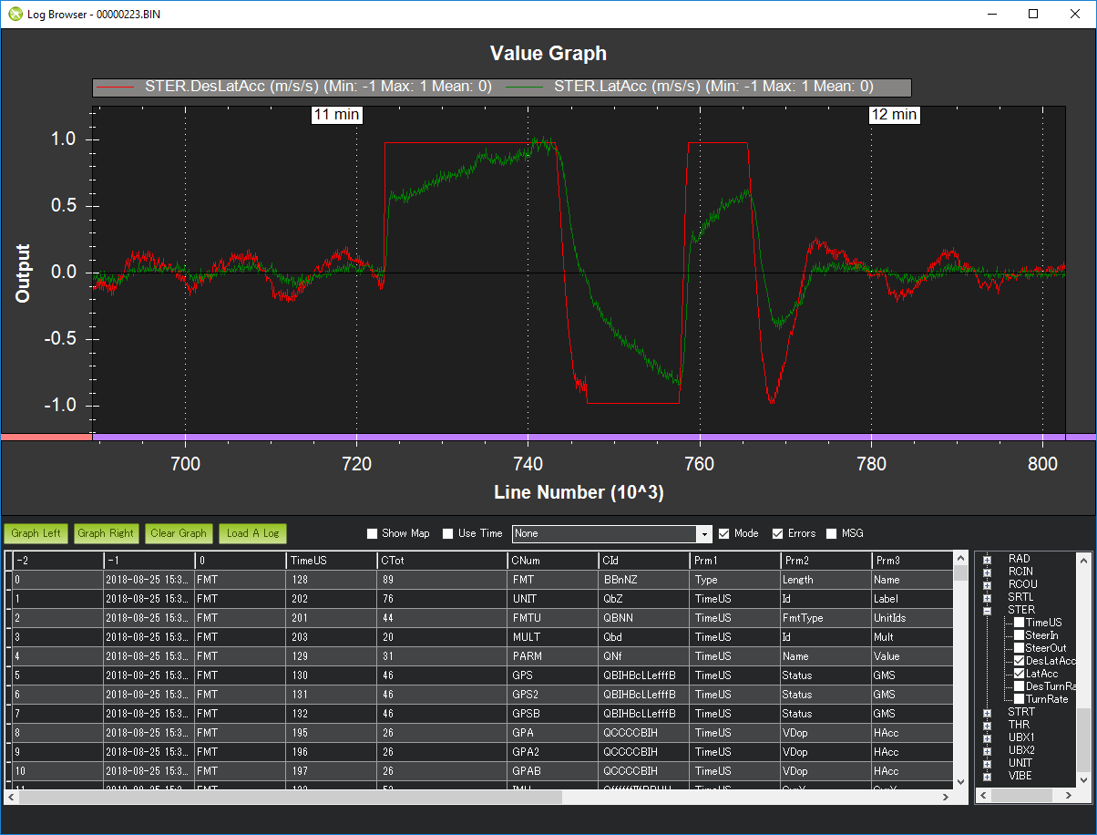
The first thing I looked at was your desired and achieved yaw. They are not quite aligning as well as they could be. They also overshoot sometimes, indicating problems.

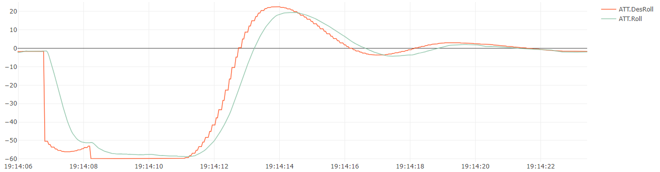
Here’s a comparatively well tuned aircraft roll graph from one of my flights. It rarely overshoots, and it moves quickly to the desired angle.

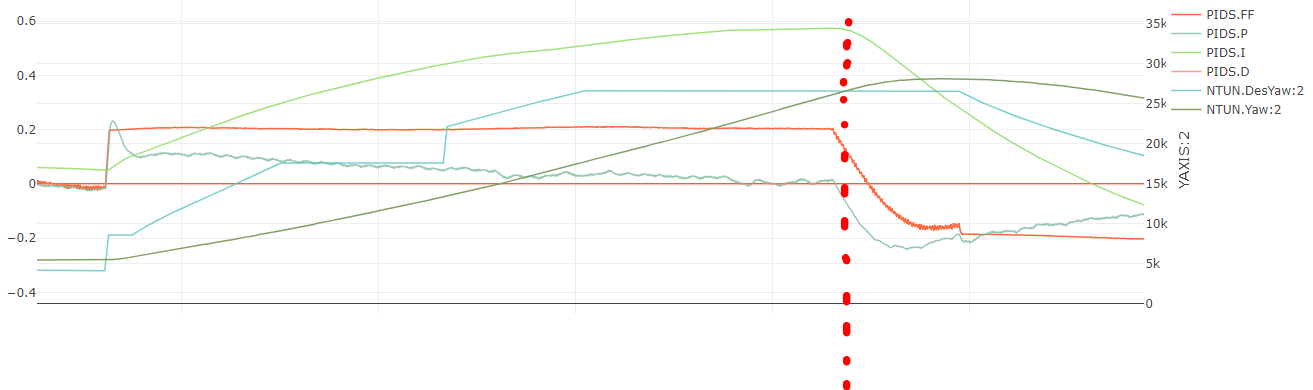
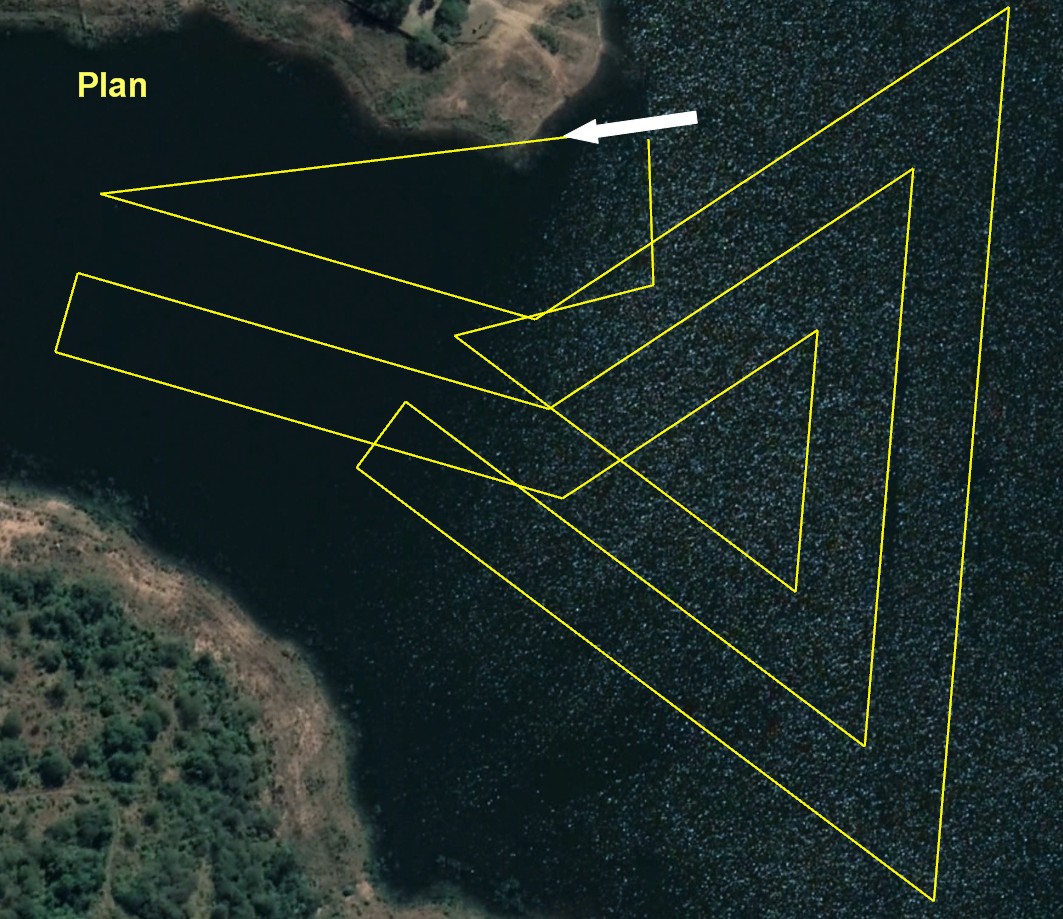
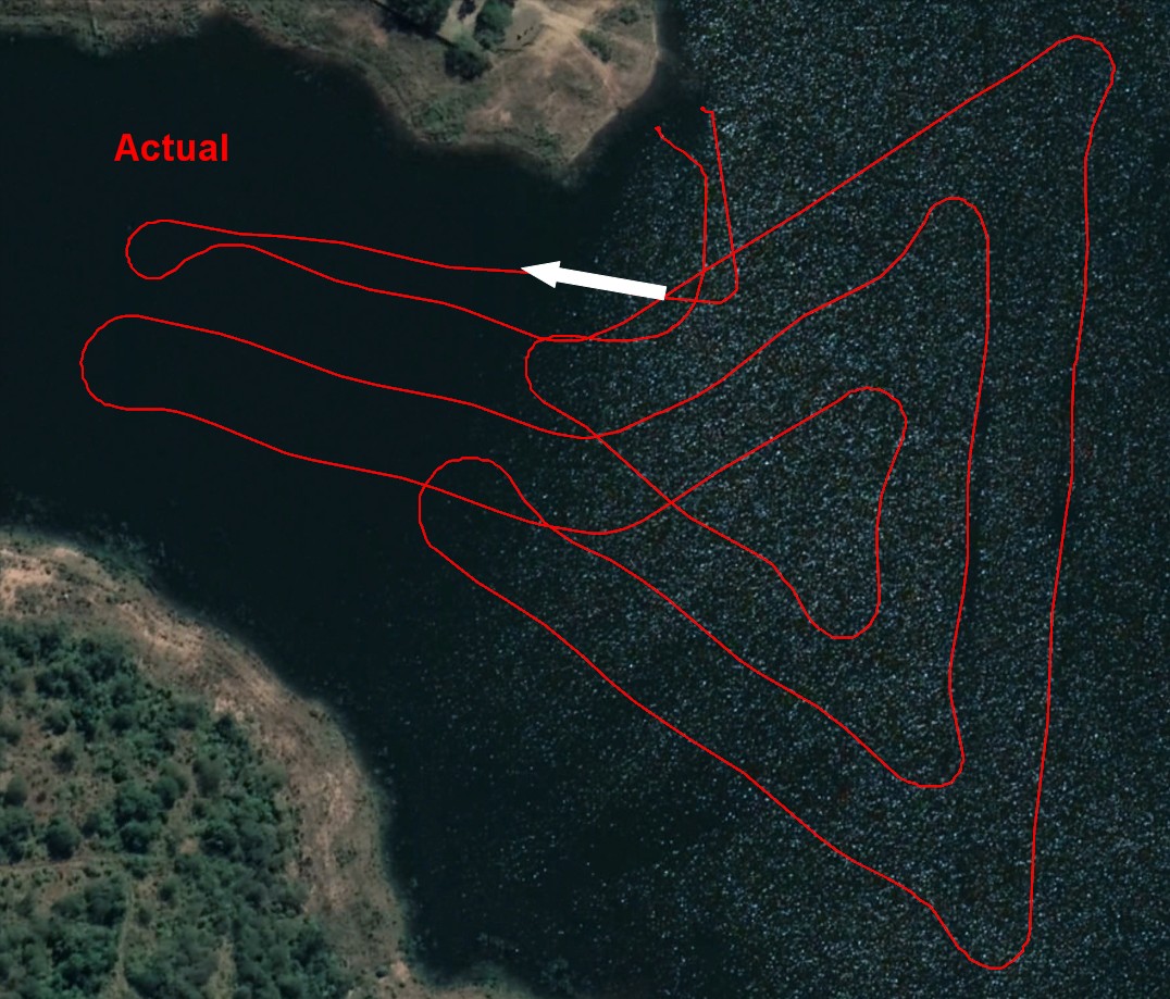
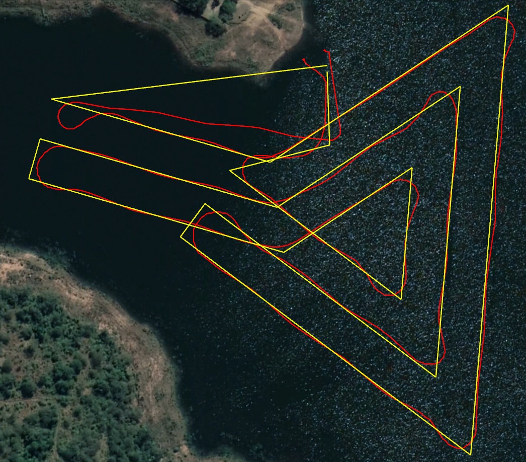
The red line on the graph of your craft is showing that the navigation controller is demanding a 270 (westbound) track and then swinging back to a 180 (southbound) track before settling on a 220 (southwestbound track). The craft is slow to achieve these headings, and often it is overshooting them. It’s actually a bit of an oscillation.

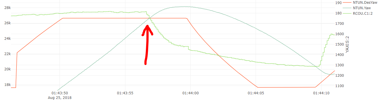
To understand why it is overshooting them, I looked at your servo 1 output. It was showing values far from trim at the moment that the desired and actual yaw met. Normally when your craft is straight, I see a consistent 1500 pwm output, and that is excellent. Here however, the PWM was about 1800 when it should have been 1500.

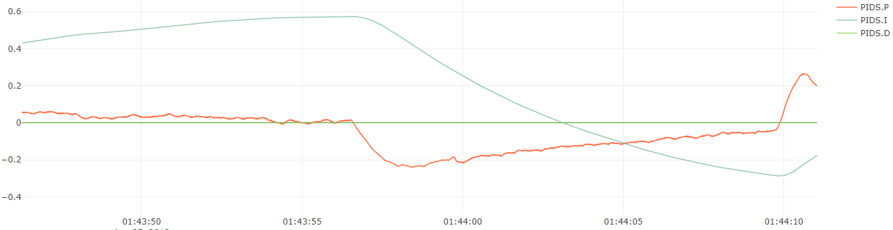
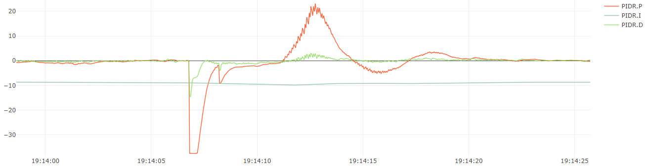
To see why the motor is still turned when the actual and desired yaw are equal, I looked at your PID.S graphs. It’s obvious that you have I-term buildup that is causing the servo motor to be far too sluggish to do the right thing.

As a reference, here is my aircraft’s roll PID chart that gives you an example of how PID’s should be. The I-term remains pretty constant because my aircraft isn’t very well in trim, but the P-value dominates when there are large roll errors (changes).

#1 recommendation: Turn down your ATC_STR_RAT_I gain. Try 0.05 instead of 0.5. This should help with the overshoot in the path just after turns.

#2 recommendation: Turn down your ATC_STR_RAT_IMAX to 0.15 instead of 1. It is obvious that your boat is fairly well in trim (better than 15% of the steering throw). This will also help prevent That I-term buildup

#3 recommendation: Turn up your TURN_MAX_G. Try .7 instead of .1. That will decrease the chance that the navigation controller is suppressed by this parameter. It’s likely that your boat can handle fairly high acceleration turns well because of its side floats and thrust that is below the waterline. Boats typically can achieve quite high acceleration turns.

#4 recommendation: Turn your NAVL1_DAMPING back down to 0.7. Having that high may cause oscillations as well, but it’s hard to tell until you get your steering to hit the desired

#5 recommendation: Turn up your ATC_STR_RAT_P value to 1.4 instead of 1.0. This should help your motor turn tighter. It is currently not maxing out when I look at the CH1 output graph. The PID values should be dominated by P-gain as shown in my roll graph above. The P-gain should do the work of turning the motor when the heading is not as desired.

#6 recommendation: Turn down ATC_STR_RAT_FILT a bit. Maybe try 1 instead of 5. I don’t know exactly how this affects the outputs, but be cautious when testing this.

AFTER you run a few test missions, and see that your desired and actual yaw are matching up well (after turns) then play with NAV_L1_PERIOD. Note that immediately after a waypoint is finished, the yaw demand will be a lot and the boat obviously can’t whip around immediately. You should, however, see your steering servo nearly max out until it achieves that desired heading. Note that the desired heading is usually up to 45 degrees from the waypoint path. It will rarely approach the new run at a steeper angle.

1 Like

Thanks for the analysis Nate,

One thing though is I don’t agree with the advice for #5 (Turn up ATC_STR_RAT_P). In rover the PID values should be dominated by the feed forward, not by the P gain. The P and I values should always be lower than the FF gain.

Randy,

I agree if your rover has positive traction. Boats, however, do not. I think either method might be effective, but in my opinion, more weighting on the PIDs would be more applicable here. Just an opinion, and we’ll see what works!

-Nathan

1 Like

The other thing I noticed was that the FF Gain may also be causing an issue. It continues to hold some FF gain even after the target yaw has been met. That seems very odd and problematic.

1 Like

And now after looking at the STER data, I understand where FF gain is coming into this mix. It’s coming from the desired lateral acceleration (Currently 1 m/s).

The I-term buildup is because the FF gain is not high enough. The desired turn rate is not being met due to the FF gain not being high enough. So increase your ATC_STR_RAT_FF. Increase it by 35%

1 Like

Nate,

The L1 controller’s output is a lateral acceleration in both plane and rover so that’s what we use. It’s converted into a desired turn rate (which is a pretty simple calc using the vehicle’s velocity) and then passed into the turn rate controller. Rover also has a heading controller which is a simple P controller which converts the heading error into a desired turn rate which is passed down into the turn rate controller… but that’s not used in Auto. It’s used during pivot turns on skid-steering vehicles though.

Hi Nathan,
Thank you so much for your input here, I get so excited to receive such valuable information and I am aware of the time and effort that goes into a reply such as yours, for this I am very grateful.

As time goes on I am starting to realise more and more how unique my craft is from a steering perspective and how hard the poor navigation controller is having to work. i.e. Trying to get the controller to achieve something that the craft itself is not capable of.

While my trim might be pretty close to spot on, I need to get to the bottom of why my starboard turning circle is 40m and port 30m, and how to get them to be both 35m for example. i.e. compensating for the screw of the propeller.

Unfortunately the steering is sluggish as the servo is turning the entire outboard motor which weighs nearly 18kg plus the friction on the steering column. I have tried the ‘fixed motor and rudder’ thing and unfortunately does not work on this hull design as it opens a whole new can of worms.

From Randy’s side, I think if the controller somehow knew what the upcoming Angle of Attack (acute, right, obtuse) was to the next waypoint and corrected the speed accordingly, not only in throttle, but time leading up to the waypoint allowing the craft to slow down in time and REMAIN slow until it is back on track, then increase the throttle back up to WAYPOINT_SPEED.

Yeah. Sorry about the confusion. I see what is going on now. For planes, bank is directly related to lateral acceleration, so that makes sense.

That should be done using Servo1_min and servo1_max. If your turns are tighter in one direction, either increase the servo travel range in the opposite direction, or reduce the range in the direction that is so tight.

2 Likes

Oh ok, I have never tried that. I will do what I can from a hardware perspective, then make the final adjustment on SERVO1 MIN & MAX

Great.

Another thing to be aware of…

Your steering tune will probably work well for one cruise speed, but at any other speed there will be some error and potentially overshoot or undershoot.

This will probably be most evident by changing the TURN_MAX_G parameter. For example, it looks like at 4m/s, your turn max g is about .15 m/s^2. That is just the mathematical acceleration of a boat turning at a 35m radius at 4 m/s. Because lateral acceleration is proportional to the square of the speed, if you increase speed to 8m/s, you’ll be turning at 0.6m/s (4 times the lateral acceleration, but the same radius). Without changing TURN_MAX_G, your new turn radius will probably be 70m, and I doubt you want that.

Makes sense Nate. Missions are generally carried out at between 3m/s for sidescan and 5m/s for general bathymetry

I agree with Nate on a few things but disagree on a few others.

Most importantly I agree with Nate though that the ATC_STR_RAT_FF is probably too low. So maybe increase it from 0.8 to 1.2. I would leave P where it is because it’s already quite high at 1.0. I think leaving the ATC_STR_RAT_FILT at 5 is also fine.

I also agree that TURN_MAX_G should be increased from 0.1… but I’d say 0.3 is probably a better number - 0.7 seems too high to me. In the graph below we can see the desired lat accel (in red) vs actual lateral acceleration (in green). The flat top on the red line shows TURN_MAX_G is limiting the turn rate and the green line does eventually reach it so we know the vehicle can do more than 0.1G… how much more I’m not totally sure.


The TURN_MAX_G parameter is really only used to apply a maximum limit on the desired lateral acceleration so it’s not something you need to tune but it’s best to set it to something close to what the vehicle can achieve.

I’m not yet very familiary about how the NAVL1_DAMPING affects performance so taking Nate’s suggestion of putting it back down to 0.7 could be fine (I don’t know) but I’d focus on getting the steering control better first.

What is a little odd is that the vehicle is not slowing down for the corners. This may be because the TURN_RADIUS is set to 15m. Could you try reducing this back to 2m even though that is unrealistic for the boat?

The CRUISE_THROTTLE should probably be raised from 5% to 14%. CRUISE_SPEED is 4m/s. By the way to change the speed that a mission is executed at, it’s best to modify WP_SPEED instead of CRUISE_SPEED.

I think it should be possible to get the steering control to work for almost any speed without re-tuning. I have not specifically tested this, and I do think there are issues below 1m/s, but above that I think it should be possible to get a tune that works at many speeds. The reason is that we have compensation for the expected response built into the motors library.

I have loaded these new parameters and will be testing again tomorrow, Thank you.

1 - What setting tells the craft to slow down when approaching a waypoint?
2 - What setting tells the craft by how much to reduce throttle when approaching a waypoint?

After briefly searching the parameters and docs, I do not see a feature that allows slowing down for waypoints.

I find this prop steer issue very interesting. The vectored thrust with a single screw also.

JohnE,

it calculates how much it should slow down primarily using:

  • ATC_ACCEL_MAX (maximum forward/back acceleration). If this is set low, the vehicle will accelerate and declerate more slowly. This will mean it will start decelerating farther away from the waypoint.
  • the higher of WP_OVERSHOOT (how far from the line between waypoints the vehicle is allowed to stray) and TURN_RADIUS.
  • TURN_MAX_G (the maximum expected lateral acceleration of the vehicle). If this is set low, it will calculate that it needs to slow down more in order to make the turn without straying too far from the line.

EDIT: by the way, I worry we will see a return of the wobbles at corners… I think the cause is actually the speed controller. we may need to lower ATC_SPEED_FILT from 10 to 5 and ATC_SPEED_P from 0.05 to 0.02 but I’m really not sure.

NateE,

The code that does the maximum speed calculation is here and here.

Randy,
Here are those settings from yesterday (4 Sep) at work …
Smoother steering and throttle but a slight sacrifice on accuracy.
Plan …

Actual …

Compared …

No erratic throttle or steering …

1 Like

I also worked on the mechanical setup on the steering an have managed to get the turning equal and circle down to 16.2m at 14kph