Is it absolutely necessary to set the harmonic notch filter?

Apologies in advance for the lots of incoming questions.

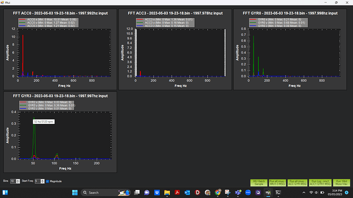
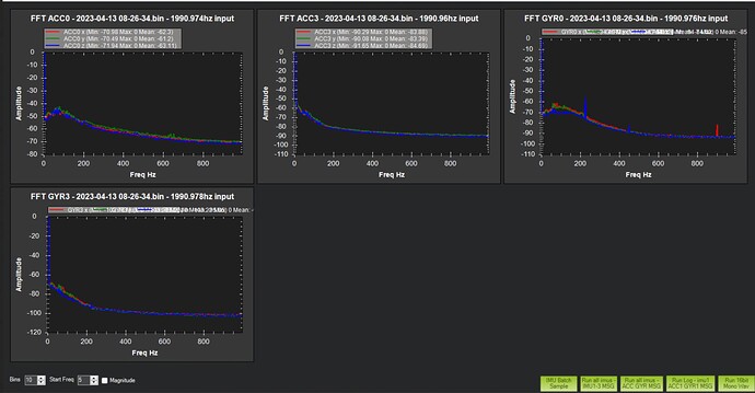
The FFT logs from our flights show that there is no noise or peak noise in Gyroscope and the Accelerometer before setting the notch filter. So, is it necessary to set a notch filter? What are the benefits of setting the notch filter?

P.S. I read something about setting the gyro filter to a higher frequency for a “tighter tune”. Is this another benefit of setting a notch filter? Is setting the gyroscope to a higher value necessary and how do we determine that high gyroscope filter frequency?

It only looks that way because you have log scaling. The benifit of the Noth Filter is described in the wiki.
Managing noise

1 Like

The notch filter will only filter the gyro noise. So you must ignore the accelerometers graphs when configuring the notch filter and only look at the before and after gyro noise graphs. LOG_OPTIONS=4

1 Like


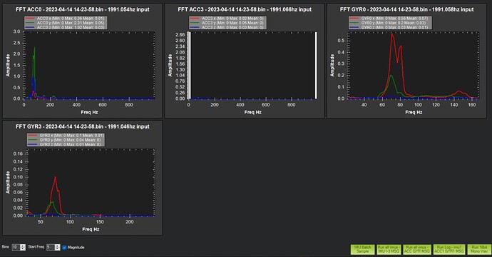
Here we can see that the frequency where the amplitude starts at 50Hz with a peak of around 69hz and ends at around 90Hz.
First of all, is it right to assume that these frequencies are corresponding to the motor hover frequencies? Second, can we use this to set up our notch filter? Third, with FFT based notch filter, are the following frequency-related parameters good values?

FFT_MINHZ = 55
INS_HNTCH_BW = 30
INS_HNTCH_FREQ = 70

Gotit. From what I can see from IMU batch sampler the peak noise is around 69Hz. From the FTN1 log, the BW is showing at 85.87 Hz. The hover frequency seems to be at 80. But the BW and hover frequency doesn’t make sense based on what I can see from the FFT GYR graph.

After enabling the FFT and flying the drone, the parameters it automatically set were as follows:

I want to change some parameters as follows based on the FFT GYRO graph. Do you think these values are alright to set?
FFT_MINHZ = 55
INS_HNTCH_BW = 30
INS_HNTCH_FREQ = 70

The link for the flight log where we set the FFT-based notch that resulted in a crash is as follows.

https://drive.google.com/file/d/1QGmrWbIDW9qouPFk7U1usE4uy8LO1YEU/view?usp=sharing

The in-flight FFT is saying 80Hz because it’s limited by FFT_MINHZ,80
when as per your graphs the peak frequency is about 70Hz, or 69

These ones you listed would be OK

FFT_MINHZ = 55
INS_HNTCH_BW = 30
INS_HNTCH_FREQ = 70

and you would need these

INS_HNTCH_MODE=4
INS_HNTCH_REF=1
INS_HNTCH_OPTS=2
1 Like

Couldnt access that log, set it to “anyone with the link”

2 Likes

Sorry about that.
The link should work now.
Please let me know if you find anything suspicious.

The Y axis vibrations are bad - so something is pulling unevenly on the flight controller or rubbing against it, usually wiring.

If you were to change over to throttle-based notch filter you would set

FFT_ENABLE,0
INS_HNTCH_MODE,1
INS_HNTCH_REF,0.2
INS_HNTCH_FREQ,69
INS_HNTCH_BW,20
INS_HNTCH_FM_RAT,0.7

This is the usually easiest option and guaranteed to give a good result.

The in-flight FFT is the most technical solution and suits changing payloads, but you will have to check the operation of in-flight FFT by adjusting some or all of the FFT_ params, and check logs to see what frequency it is detecting - should be 69Hz in your case.
You will have to read up on each of the FFT_ params in order to help it target the correct frequency.

FFT_MINHZ,40 // start by setting this
INS_HNTCH_MODE,4
INS_HNTCH_REF,1
INS_HNTCH_FM_RAT,1
INS_HNTCH_FREQ,69  // these dont really matter for using FFT
INS_HNTCH_BW,20  // they will be dynamically set

and

INS_HNTCH_HMNCS,3
INS_HNTCH_OPTS,0

or

INS_HNTCH_HMNCS,0
INS_HNTCH_OPTS,2 // this puts a notch in for every detected peak, making the HMNCS parameter redundant

The option I think you SHOULD use is ESC RPM based notch filter. Also very easy to configure since you already have the ESC telemetry working, and it works with different payloads because the motor RPM drives the notch frequency - best of everything!

FFT_ENABLE,0
INS_HNTCH_MODE,3
INS_HNTCH_FREQ,69
INS_HNTCH_BW,20
INS_HNTCH_FM_RAT,1
INS_HNTCH_REF,1
INS_HNTCH_HMNCS,3
INS_HNTCH_OPTS,0

The trick even with ESC RPM based notch is the frequency and bandwidth - as the frequency changes with RPM, the bandwidth is also scaled in proportion to the values you set here. As RPM goes up the bandwidth will get wider. So it’s important to get the bandwidth correct and use only the minimum required bandwidth.
If you use INS_HNTCH_OPTS,2 you get a notch per motor, which is usually not needed and can start to have undesired effects. In some cases this will be appropriate.

Setting up the Harmonic Notch Filter correctly will allow better tuning.
Better tuning gives best use of battery capacity and you are able to easily see if any issues develop.

1 Like

Thank you for the clarification on setting different modes of the notch filter. We are going with FFT for now. Will let you know if we run into any issues.

Be sure to fix the vibration issue before you go any further.
If in-flight FFT gives you any trouble, fall back to using ESC RPM for harmonic notch filtering and disable in-flight FFT.

1 Like

It seems like the wires connected to the motors through the flight controllers had a loose connection. Not sure if this causes the vibration but we have made a secure connection now.


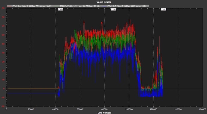
This is the SNR in the previous flight. The mean for SnZ is 15.7 which is below the FFT_SNR_REF = 25dB. Should we reduce this to a lower value? I can see that the majority of the value seems to be above 25 dB but right around the end there are some values between 0 to 20.

can you also explain what INS_HNTCH_OPTS does and should we change this based on the mode of the notch filter?

Thank you!

I would say the mean values are skewed because you are including a part of the log where the copter appears landed (??) . Use the selection cross-hair to just select the part of that graph where the copter is clearly flying and you’ll get more realistic mean values.
You existing value for FFT_SNR_REF should be fine.

Let us know what you end up with for all the FFT parameters and the HNOTCH results.

Hi, I am working with a quadcopter and have tried to set up the In-Flight Dynamic FFT Notch Filter and irrespective of what values I tried for the FFTMINHZ, the notch center frequency, and bandwidth to get rid of the noise shown below.

INS_HNTCH_FREQ was set to 52 Hz in the first flight, and INS_HNTCH_BW was set to 10 Hz. This did not get rid of the noise at 52 Hz.

INS_HNTCH_FREQ was set to 80 Hz in the second flight, and INS_HNTCH_BW was set to 10 Hz. This did not get rid of the noise at 22 Hz.

The logs can be found here.

Is there any reason why the filter did not work? Or was it not set properly?
The drone build is a quadcopter with 10 in (2 bladed) props.

The inflight FFT seems to have trouble getting down below 80Hz without some special attention. I believe there’s an improvement on the way. When you have INS_HNTCH_MODE = 4 then it doesnt matter what you put for the Freq and BW values.

Normally the frequency associated with 10inch props is about 90 Hz give or take.
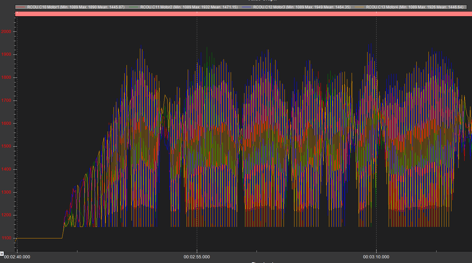
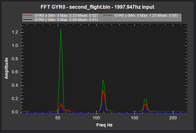
So the 54Hz peak in this graph is likely a side effect of the bad motor oscillations seen in the next pic.
The 109Hz peak is closer to the true value, but with those oscillations we can not tell for sure yet.
image

Bad motor oscillations

Most of the problems will be caused by this X axis vibration. You will have to take positive steps to solve this before more flights. It could be prop or motor balance, or wires pulled tight to the flight controller, or something touching the flight controller. provide a couple of photos if you can.

For the filter I suggest you set:

FFT_ENABLE,0
INS_ACCEL_FILTER,10
INS_HNTCH_MODE,1
INS_HNTCH_REF,0.14
INS_HNTCH_FREQ,90
INS_HNTCH_BW,45
INS_HNTCH_FM_RAT,0.7
INS_HNTCH_HMNCS,3
INS_HNTCH_OPTS,0

And to tame the oscillations a bit and hopefully improve stability

ATC_ANG_RLL_P,6.0
ATC_ANG_PIT_P,6.0
ATC_RAT_RLL_P,0.11
ATC_RAT_RLL_I,0.11
ATC_RAT_RLL_D,0.003
ATC_RAT_PIT_P,0.11
ATC_RAT_PIT_I,0.11
ATC_RAT_PIT_D,0.003

EDIT:
I see you do have BATT2 voltage and current monitoring, I must have missed it.
I cant tell exactly what sort of battery you have though, the voltage values you have dont quite match any normal values. What battery is it?
end edit

I highly recommend you configure the BATT voltage monitoring at least, and current if you can. This gives

  • thrust scaling → MOT_BAT_VOLT_x
  • safety → BATT_x_VOLT , BATT_FS_x
  • useful diagnostic data

Your Cube should have come with a “power brick” and it will be a simple matter to enable the BATT monitor, defaults will work for you.
BATT_MONITOR,4
After you enable a battery monitor, you need to reboot the flight controller, then connect to MissionPlanner / Initial Parameters and put in you battery cell count and check the chemistry type. Also select “Suggested settings” and accept all the voltage and safety related values it offers and “Write”. No need to accept any of the Accel or filter related values since you have them already.

Since you are using DSHOT you should also set up the BLHELI telemetry data - this is invaluable. It’s quite easy too - just connect the “telem” wire from the ESC to a spare serial port, RX pin. If you have individual ESCs you can join all their telem wires into one then to the serial port RX pin. The ESCs all communicate together to the flight controller on just one telem wire.
And set these according to your serial port number:

INS_HNTCH_MODE,3
INS_HNTCH_REF,1
SERIALx_BAUD,115
SERIALx_OPTIONS,16
SERIALx_PROTOCOL,16

You can even set the BATT voltage monitoring to use the ESC data if you dont have any other voltage monitor.

Dont race out and do another test flight until you are sure the vibrations are solved, or at least improved a lot. But you can set ALL of the parameters I’ve provided ready for the next flight.
Use Stabilise mode again, and if behaviour is good then use AltHold mode for a while and do some gentle pitch and roll. This flight will allow us to check and adjust the harmonic notch filter and more.
Actually this is not true. INS_HNTCH_FREQ still represents the lowest frequency used by the notch and the ratio of this to BW represents the shape of the notch

Okay, thank you for shedding more light on the FFT parameters and the notch filter.

Regarding the X-axis vibration, I believe the cause is the Here3 GPS cable is tied close to the cube orange, we’ll try to improve this and hopefully, that fixes the vibration. I will get some pictures and send them soon.

We’ll work on setting up these values for reduced oscillations and better stability once we’ve figured out the cause of the X-axis vibration.

We have already been able to configure the Battery monitor using the power2 slot of the cube orange and the power brick module that comes with the cube orange.

Regarding ESC telemetry data, I do not believe our ESCs have a telemetry wire.

Thanks Andy - I hadnt realised that about the dynamic FFT use-case.
So it’s still important to set Freq and BW very close to being correct.