Is AUTOTUNE for TRADITIONAL HELICOPTER in sight?

Blockquote

The max allowable rate D gain was calculated to be 0.0035. Data from the tuning I did a year ago, showed that I went to 0.003 before stopping because of the feedback oscillations.

Bill,
that looks so brilliantly close to me. Thanks a lot!

looks awesome, how do you stimulate the oscillations ?
I suppose you look at the enlarge scale data in order to see the behavior, could you add some graphs to elaborate us ?
Many thanks for your fine work :slight_smile:

It is really amazing to see the progress of your work, Bill! I hadnā€™t thought, that having a working autotune feature for traditional helicopters would be possible in the near future. As we can see now, you WILL make that possible. Awesome work!

1 Like

Awesome Work @bnsgeyer!!!

2 Likes

Another update on the heli autotune front. So I have been struggling with a way to take the knowledge of maximum gain for Rate P and Rate D and determine from that the ideal value that would provide the optimal response. Still havenā€™t figured that out.

But I decided to put the new sys ID mode to use to quantify what makes a good tune for heli. What gains pay the biggest dividends in making the actual attitude follow the desired attitude and what provides the best disturbance rejection. So I did a little parametric study between Angle P gain and the tuned rate controller. I varied Angle P from 4.5 to 6 and the rate controller PID gains from all being zero to my ideally tuned values of Rate P = 0.05, Rate D = 0.001 and Rate I = 0.1. I used the recovery roll SysID mode. I looked at two metrics for a good tune. First is the desired angle to requested angle. With this plot, you want the gain to be as close to 1 or 0 db and the phase to be as close to 0 deg through out the frequency range. Both the gain and phase will drop off at some point so I was just looking to see how well each did. The other criteria was disturbance rejection. With disturbance rejection, the input is the disturbance angle and the output is measured roll angle minus the disturbance angle. At low frequencies the actual angle can stay with the disturbance angle so the output (measured - disturbance) is very small compared to the input. As the frequency increases, the aircraft can no longer keep up with the disturbance input and output becomes greater than input. The goodness of disturbance rejection is measured by the frequency at which the plot crosses -3 db gain.

So here is the first one, the frequency response of desired angle to actual angle.


synrrsp4 - zero rate controller gains with angle p of 4.5
syntrsp4 - tuned rate controller gains with angle p of 4.5
synrrsp6 - zero rate controller gains with angle p of 6
syntrsp6 - tuned rate controller gains with angle p of 6

So it is interesting to note that the angle P has the biggest influence on how well the actual attitude keeps up with the desired attitude. And you can also see that the ideally tuned rate controller gains have very little to contribute to this. They contribute some to the Angle P of 4.5 but contribute very little if nothing to the Angle P of 6. It looks like the tuned rate controller gains do help some in retaining phase as you pass through the flap regressive mode at approximately 20 rad/s and definitely helps out at the frequencies above 30 rad/s but the Rate P and Rate D are actually destabilizing the lead-lag regressive mode at 50 rad/s.

Next is the plot for disturbance rejection. I only show the magnitude plot.


the definitions are the same and I used the same plot order. So if you look at -3 db and the frequency where each one passes. The tuned controller gains with Angle P of 6 has the best disturbance rejection. Showing that it can handle disturbances out to a little more than 4 rad/s with the zero rate controller gains with Angle P of 6 having a disturbance rejection of a little less than 4 rad/s. Again there is a larger difference between have the tuned rate controller gains and zero gains for angle P of 4.5.

What Iā€™ve concluded from this is using a higher Angle P provides better following of desired angles and better gust rejection. Also Rate P and D gains provide some improved response but they are not all that critical. Certainly they help somewhat tame the flap reqressive but excite the lead-lag regressive. I know some spend many hours flight testing (myself included) trying to squeeze out just a little more Rate P and D but Iā€™m not sure that this is all that critical for a good tune.

I have a little more to share but I will post this for now.

1 Like

The last part of my investigation looked at the command model influence on desired vs actual attitude compared using Sys ID mode 1 to the recovery roll (sys ID mode 4) response.

what is interesting here is that the command model even though it uses a angle P of 6 with the ideally tuned rate controller gains, has a similar response to the response with no command model and an angle p of 4.5. So this tells me that I could change my command model to get a better response up to what is achieved with no command model.

4 Likes

Hi Bill!

Those are super interesting results. Thanks for sharing your progress.

Although this is definitely a really complex problem (and I think I still donā€™t understand all the effects that are happening there), I got an idea of how valuable your frequency response tests are.

Iā€™m sure that I speak in the name of all TradHeli users when I say thank you so much for your effort!!

5 Likes

Bill,
I totally agree with Felix.
Also I herewith thank you very much for what you are doing for all Trad Heli flyers!!

2 Likes

Great work @bnsgeyer, thank you for your devotion and knowledge sharing,
Can the auto tune procedure be done in two steps ?
finding the best P and later fine tune the I and D ?

1 Like

@ZvikaF I think that there will be a distinct order for the gain tuning and one step will build on the other. It could be done in steps but I am hoping the autotune will be fast enough to do a complete tune on one axis within 5 to 7 min

3 Likes

Tradheli enthusiasts,
Writing to provide an update on my progress. Currently I am still testing to see what combination of Ang_P and Rate PID gains provide the best tune for a helicopter. I think Iā€™ve got a good idea now and hope to start hacking away at the autotune feature.

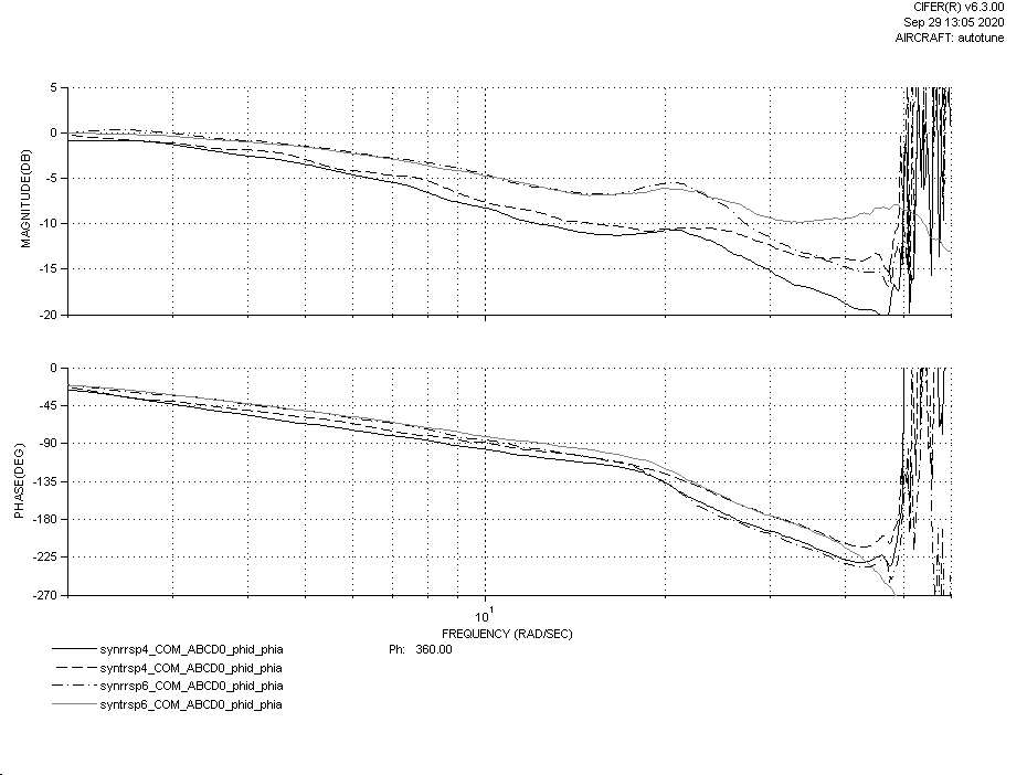
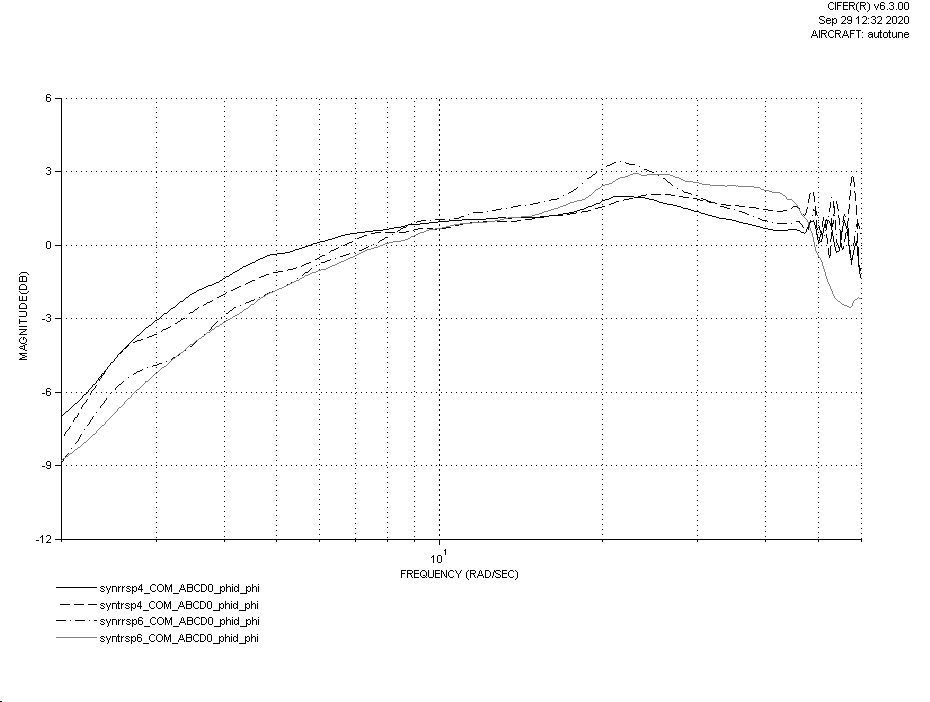
In my previous post, I was attempting to show the importance of the Ang_P gain versus Rate P or Rate D in providing good adherence to the desired attitude as well as good disturbance rejection. That is still my belief and I have adjusted my plots to better show the this. Previously I was conducting the analysis using the pilot stick commanded angle to the actual aircraft angle. I realized that although this shows what the pilot would perceive as the aircraft response, the judge of a good tune is how well the aircraft responds to the attitude command after the shaping or command model. You set the INPUT_TC and ACCEL_MAX parameters to adjust the ā€œfeelā€ of the aircraft and keep the requested response within the capabilities of the aircraft. The ANG_P and rate PIDs are designed to drive the aircraft to that command model output and doing the analysis with respect to the command model input provides a best assessment of the goodness of the tune.

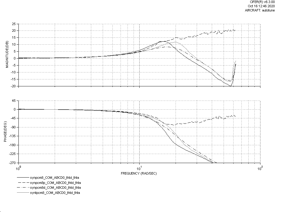
I revisited the effects of Ang_P, rate P and rate D on the response. Mostly I looked at individual contributions of rate P and rate D to the tune in both pitch and roll axes. Below is the bode plot for the pitch axis showing just Angle P, Angle P with rate P, Angle P with rate D, and then the final tune with rate PID. Angle P was set at 8.

synpcm8 - just angle P
synpcm8p - angle P and Rate P =0.03
synpcm8d - angle P and rate D=0.0025
syntpcm8 - angle P with PID gains

First I will note that when I attempted the angle P with rate P gain, I got pretty large oscillations which forced me to abort the sweep. I am not sure why the bode plot looks that way unless the large oscillations excited response across the frequency spectrum but I would have expected the gain and phase to drop off about the point where I aborted the sweep which was probably around 20 rad/s. Regardless my take away was that P gain alone with Angle P increases the amplitude at the flap regressive mode. The desire is to reduce the peak that in the plot of angle P alone. You can see that rate D does exactly that. Now the plot of angle P with rate PID does not exceed the peak of angle P alone but if no rate P was used, then that peak would be lower and proved a better response.

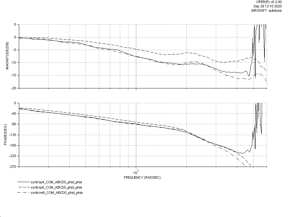
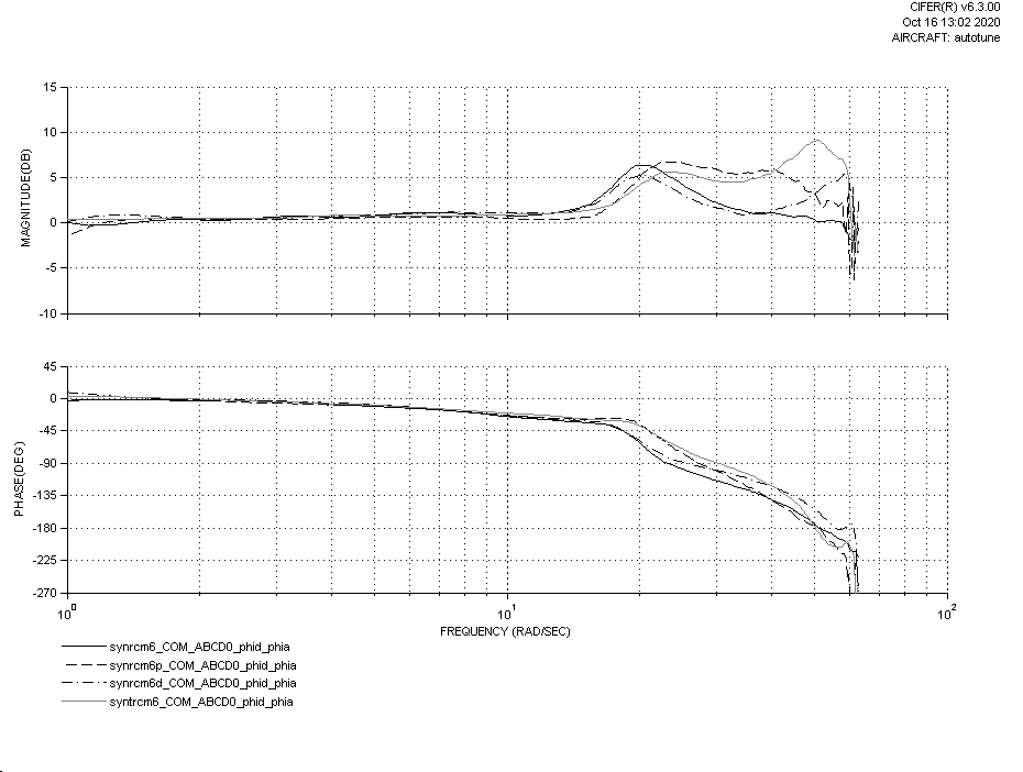
The next plot is for roll axis. The sequence of signals is the same. Angle P was set to 6.

synrcm6 - just angle P
synrcm6p - angle P and Rate P =0.05
synrcm6d - angle P and rate D=0.001
syntrcm6 - angle P with PID gains
This shows similar trends. Adding P gain does not help reduce the peak compared to angle P alone. Adding D gain does reduce the peak however I learned that it also excites the lead-lag regressive at around 60 rad/s (you can see the rise in the magnitude plot as it goes out to 60 rad/s). So that is something that will have to be watched when raising D gain. you can really see the lead lag regressive peak in the plot of angle P with rate PID where the peak in the magnitude is about 50 rad/s.

So based on what Iā€™ve done to this point, the goal for the tuning of pitch and roll is to raise the Angle P gain to at least 6 or more. I donā€™t know if I would recommend going above 10. I expect as the angle P gain is raised with no rate PID, youā€™ll excite the flap regressive and it is fine to leave the response a little oscillatory. Then you can raise the rate D gain and that should remove some of the oscillatory behavior until you start adding too much and get instability. Iā€™m not convinced that rate P gain is beneficial to a heli tune.

I know I havenā€™t considered phase much in this analysis. rate P gain certainly reduces the phase loss but my thought is that phase loss could be reduced by increasing angle P too and using rate D gain to keep the peak of the magnitude down. Thus you would not need to use rate P and I think there is more benefit in disturbance rejection to having more angle P vice having any rate P at all.

5 Likes

Tradheli users,
Just wanted to provide an update on this effort. Over the past few months, I was primarily working on splitting the multi and heli autotune code. It made sense to show the Devs that the multi code was not broken by the introduction of the heli code to the autotune library. Plus it makes it a lot easier to check for errors if all the changes are just related to separating out heli and multi frames in the library without the additional code of heli autotune. I have completed the split and am hoping that it will be merged soon. Here is the PR that splits heli and multi autotune.

So I hope to get heli autotune into the 4.1 release but we will see. I think I have all of the tools coded, it is now deciding how to order the tuning process and making the decisions on gains. Also there will be LOTS of testing involved. And along that line, if there is anyone willing to test alpha version software of the heli autotune, please let me know. I can get you a copy once I get to that point. I mainly have 600 size heliā€™s. So I would be looking for those that have smaller, like 350-450, and larger, 700-800 size heliā€™s. I would also be interested in those that are flying tandems. I know this is a lot to ask as it will mean higher risk testing. Thanks in advance.
Regards,
Bill

2 Likes

Hi Bill,
Thanks for the update, thatā€™s great news.
I would be willing to test the new heli autotune on my Goblin 380 and 770 if you still need testers?

Today, I installed 4.0.6.rc1 and did some tuning and playing with the notch filter on the 380. In the end, I wasnā€™t happy with loiter and my tune so will have another go tomorrow.
Regards,
Steve

1 Like

Hi Steve,
That would be great. It will probably be another month before I have something ready to test but I will definitely take you up on the offer. Iā€™ll be in touch.

Let me know how it goes
Regards,
Bill

Excellent news @bnsgeyer

I would be willing to check the autotune in one of my 450.
Did you implement Dr. Tischlerā€™s code ?

2 Likes

@ZvikaF Are you familiar with CIFER? I have been using CIFER to look at the frequency responses to analyze what makes a good tune. I had also used CIFER to make a rotor model of my Synergy 626 Heli. The SITL in master has a rotor model that includes the rotor flapping states. I have an improved model that includes lead-lag but I havenā€™t pushed that to master yet. I have been using it to help further develop the autotune code.

Tradheli users,
Another update on heli autotune. Made considerable progress. I think I am ready to start testing with those that want to help out. I just finished up some flight test today with the latest version that was backported to 4.0.6. The autotune is set up to only tune VFF and Angle P. I think this would make a good first release. Then I can follow up with a subsequent version that will tune Rate P and Rate D. Here is a video from today where autotune was tuning the pitch axis. It takes about 3 minutes to do the tuning on one axis.
https://drive.google.com/file/d/179IWneFgip4iFjn5B0jH9wK2tK5M7fJ2/view?usp=sharing
There are two maneuvers that are involved in the tuning. The first is looking at a constant rate going from 20 deg nose up to 20 deg nose down. This is used to determine VFF. The second maneuver is a series of oscillations at increasing frequencies. During this maneuver I found the aircraft drifting quite a bit and wasnā€™t able to finish the maneuver before I had to manipulate the controls to keep it from hitting anything. So I added a feature to this test which allows the pilot to make small corrections while the test is being done. The pilot just wants to stop the drift which requires just holding a small amount of stick input to keep it from drifting. It works really well shown by the fact that I have a small back yard (50 ft by 50 ft).

4 Likes

@bnsgeyer
We had a long talk with Mark Tishler, I have not used CIFER yet, might use it later to get Trex-550 parameters, might also use Stitching to try and get agile autopilot.
Understood from Mark that you implemented some of his ā€œcā€ code in the autotune :slight_smile:
Great news about the autotune, looking forward to see it work.
Wonder if it will get better parameters to my 450 type.

Video looks great, i see you have authority during the longitudal swap.

@ZvikaF

That would be great! You will probably want to use the SysID mode to gather the frequency sweep data. The way it is currently implemented, it uses stabilize mode and inserts the sweep at different points in the code depending on the axis selection. The only problem that this creates is the inputs are highly correlated which is a bad thing for developing the bare airframe model unless you use CIFERā€™s new feature Joint Input-Output Method. It manipulates the data to decouple the response and provide the frequency sweeps you need to develop a bare airframe model. I havenā€™t seen the update to CIFER yet that provides this capability.

I did not implement code from Mark for autotune. He may have been thinking of SysID. I think the chirp function from SysID comes from the Army but Iā€™m not certain of that. I had spoken to an Engineer in Markā€™s group about creating a real time frequency response generating algorithm. It would make what Iā€™m doing a whole lot easier however it would require running the algorithm on a separate thread like the real time FFT work. I think that is something to consider in the future. It would make it very easy to determine instabilities and isolate them to specific frequencies. I am doing a lot of time domain gymnastics to pull out the phase and gain for each dwell.

I think with a little more refinement, it should give most users the 80-90% solution.

@bnsgeyer

Yes, we thought of the decoupled version, Mark thinks we can get the coefficients from two or three points

Sounds like a good task for a companion processor, raspberry pie might be able to do that.
looking forward to see it work