Felix,
I believe there were 2 main factors for that. My collective negative was not set right. The Heli did not get a push to the ground. The other reason are the 3 blades. They are asymmetric ( totally flat under neath ). In slow motion I could see that the blades are flexing badly.
After I fixed the Heli I tuned with half symmetric German Spinblades and without any incident. (Also now with a different Align 2 blade head).
After that I changed back to the scale blades also from Germany ’ Der Blattschmied.
It needed a bit re tuning. But now it is flying very good.
Yes, I saw that too. It looks like the rotor is in a ground resonance. The lead-lag motion of the blades is excited by the bumps coming from the skids bouncing off from the ground. I think three bladed systems are generally very vulnerable to ground resonance problems. Here you can see a manned Helicopter in the same situation:

What a experience for the people inside of that Helicopter! Terrible.
WOW … great news, thanks for all the updates and insights.
Tradheli Users,
I am pleased to announce that I have begun the initial flight test of the heli autotune. Today I completed two flights and there was plenty to learn from them. This may be a bit of a journey in getting this to you. But I have to do the necessary testing to make it robust. Sorry I don’t have any video but my main concern was just making sure I could do this safely. I will try to get some video as I gain more confidence in the autotune feature.
I conducted today’s test with autotuning the roll axis. I chose this axis because it is better behaved (more natural damping) than the pitch axis. I configured the pitch axis with gains I set through manual tuning. As you probably know, the pitch and roll axis are very coupled and I wanted to have the autopilot help me and the autotune in the pitch axis while tuning the roll. Yaw was also using gains I determined through manual tuning. In the roll axis, I start the autotune with the FF gain set to 0.15 (our recommended initial setting) and the Rate P and Rate D gains were set to zero. I kept the ANG_P gain at the default setting of 4.5.
In both flights, the autotune made it through the FF test and set the gain and then started the rate D test. I was pretty happy with that even though in both flights it didn’t finish the Rate D tuning before I had to land due to low battery.
With the FF test, it took some time to determine the gain. The test consists of rolling 20 deg right bank angle and then commanding a constant roll rate of 50 deg/s to the left until it gets to 20 deg left bank angle. The idea is to have the aircraft stabilize at the 50 deg/s while rolling to the left to determine how much command is needed to keep it rolling at a constant rate.
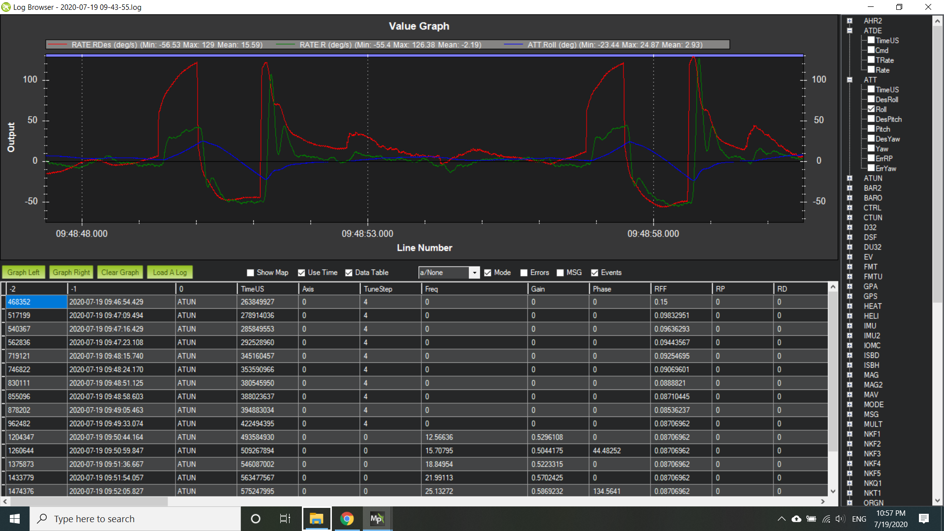
Above is an example of the maneuver showing desired rate, actual rate and actual roll angle. I thought that part of the issue with it not finding the rate quickly dealt with target getting very large to the right and then reversing. Notice how it gets to nearly 100 deg/s. That is the attitude controller increasing the rate to get the aircraft to the desired rate. So I decided to remove the attitude controllers input and just have it command the desired rate of 50 deg/s. On the second flight, it determined the FF gain in two iterations. The FF gain it landed on is much higher than in the first flight.
I would say that the FF gain of 0.15 seems to be the better choice in this second flight. I may have to modify how it determines the steady state. Right now it is just looking at the values just before it reaches 20 deg left bank.
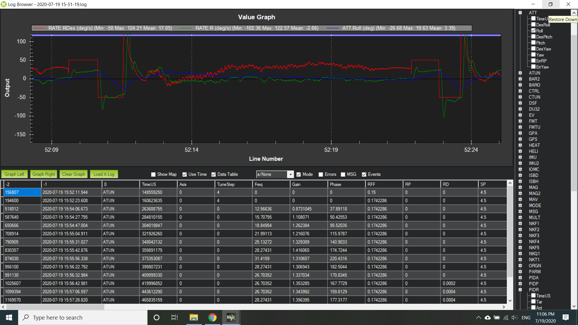
I was pretty happy with how the rate D test did. Probably the hardest thing that it has to do is take an oscillation and determine the peak and valley for one oscillation. Then it has to do it for the desired and actual rate and determine the ratio of the desired to actual amplitudes (peak to valley). Also determine the phasing between the occurrence of the peak of the actual rate after the desired rate. In simulation this was pretty easy as there was no noise in the signals. I did introduce noise in the signals in simulation just to test the robustness of my algorithms and they did pretty good. So here is a sample of what the rate D test does. It is called a dwell test because the desired rate is an oscillation at one frequency. It looks at the last 5 oscillations and averages the gain (amplitude ratio) and phase between the desired and actual.
If you look at the list of data below the graph, the dwell shown is the second to last row. You can see the gain is 1.344 meaning the amplitude of the actual rate was approximately 35% larger than the amplitude of the desired rate. The phase was 160 deg which means the actual rate peak was occurring 160 deg out of phase with the desired rate.
The part that is puzzling me now is that as it increases the rate D gain, I expected and saw in simulation that the gain (amplitude ratio) would increase. I use an amplitude ratio of 2 as the endpoint. It got to a rate D gain of 0.001 and the amplitude ratio hadn’t changed much from 1.35.
One of the biggest issues I had today was having the aircraft maintain position in between tests and during the test. I was not seeing this as much in the simulations that I had done. So I will look at the gains used between the tests, in particular the I gain. The desired roll attitude was hover roll trim but the I gain was zero during those times. I think I will invoke all of the I gain between tests to help keep the autopilot maintain the bank angle and keep the aircraft from drifting due to tail rotor thrust.
That’s all for now.
9 Likes
This is pretty great Bill! Thanks for all your work on this and sharing the progress along the way!
Since you had to land before testing was done with its cycle, I find myself wondering if AutoTune will save “completed” VFF before moving to Rate D, and then save “completed” Rate D before moving to Rate P, etc., or if the operator will need to extract those values from the logs in the case of interrupted tunes? I can see the argument for permanently storing those values along the way and not requiring the landing/saving procedure for each term, but in fairness I can also see the argument for not and am curious your thoughts.
2 Likes
Yes this is very exciting work. I’m happy to share plus it serves as a log for me to review my progress.
Currently it does not save the progress if it doesn’t complete tuning an axis. And I’m pretty sure it doesn’t do it for multicopter either.
Wow, good question. I do think there would be benefit to saving the VFF gain. This is a pretty independent gain to set and this autotune sequence makes it pretty easy to find. As for rate P and D gains, I will have to wait and see what I learn from doing an autotune on an actual heli. There may be a way that I could determine the desired gain right after doing the dwell sweep rather than stepping up the gain incrementally until I see certain criteria satisfied. So I’m hoping to be able to streamline the process. We will see!
There is the potential to make tuning VFF a seperate tuning axis, especially if you get that working before the PID values. This would let people to a VFF tune on roll and pitch, then do PID tuning on roll and pitch separately. This may let you get VFF tuning on heli done pretty quickly.
VFF tuning on Heli would dramatically improve many peoples tune!
So you would then be able to do the save at the end like we currently do, check VFF then go onto tuning the PID values.
I am thinking of using the 4th to 6th bits of the axis bitmask. But as I have talked to you about before, I would also be happy to only ever tune one axis at a time giving us 255 possible axis we can set rather than 8.
Totally agree! I think about taking it one step further to tune the phase parameter for the swashplate. This would help in removing coupling between the pitch and roll axes but only for the commanded responses. The aircraft will still have a coupled response to disturbances. But I think it would be a big improvement.
I was going to ask this and then thought, “Man, this sounds dangerous, and if it doesn’t go well it will crash many helis and then Bill will blame me for incepting the idea, and then I just have to blame Leonard again, because Leonard.” So I didn’t ask, but I’m happy you got there on your own! ![]()
It is pretty evident when you look at the logs. Pilot makes a pure pitch stick input and gets a roll response in addition to the pitch. The big thing is determining what is coupling due to the setup and then what is coupling due to rotor response (phase lag not 90 deg). I think it could be done safely but could get a little messy because of all of the other potential way users could introduce coupling in the mechanical setup. Definitely considering it.
2 Likes
Looks great, thanks for sharing.
I’m in the process of tuning my 450 with the pixhawk, making step commands and also oscillation tests. keep up the good work and keep us informed as the way of getting to the autotune is fascinating as well.
my next step it to fly a flybarless version, commanding FBL controller to ease up the process.
Will do. Thanks for responding.
Bypass using a FBL with ardupilot. It is not helpful. you will be able to safely fly your heli in stabilize with the Rate P & D gains at zero and VFF set to 0.15 and the I gain to 0.1 for the pitch and roll axes. Then you can follow the tuning guide or post for additional help.
2 Likes
Thank you for the quick response and helpful information.
Did you fly FBL with ardupilot ? I could not find any reference, actually Heli auto flying info is scares.
I thought using the FBL controller to augment stability.
No, I have never used an FBL with ardupilot. Here is the wiki for helicopter tuning as well as numerous threads within this forum about tuning helicopters.
if you are referring to auto mode, you need to spend time tuning the controller before doing any auto mode flight. What type of auto mode information are you looking for?
1 Like
Hello! I am an open source helicopter enthusiast from China. There are many problems about the use of traditional helicopter flight control, especially engine power and speed control. English is limited. Is there any other way to contact you? Like QQ WECHAT and other chat software?
翻译来自彩云小译
Thanks for the Wiki … I’ve seen it before actually i’m following the recommendation and checking of the heli response during the hovering stage right now.
dealing with small tail oscillation.
I have tried the stabilized,acro, alt hold and eventually will try the loiter mode.
The goal is flying a mission and maybe later to add external automatic mission commander controller.
I was looking for info about heli flying projects, that may help me understand the way others did it.
checking loiter on a grounded heli is quite awkward, as it seems, that the heli is not affected by the radio commands, nothing i command moves the swash plate ??? is that OK ?
That is perfectly normal. Not sure what you are trying to check with loiter. You would need to fool it into thinking it is flying. The engine doesn’t need to be running but motor interlock has to be enabled (so disconnect the power to your engine) and you would have to raise the collective above mid stick to make it think you initiated takeoff. Again, not sure what you are trying to learn. Your stick inputs don’t directly control the swashplate. Generally the way I get a new heli to auto mode is that I tune in stabilize and make sure that I’m happy that the actual attitude in the log follows closely to the desired attitude. Then I move to althold and ensure that the aircraft holds altitude well. Once i’ve completed those two steps then I will look at loiter in flight. Pull the logs and make sure that the aircraft actual position and velocities are following the desired position and velocities. Once I am happy with that, then I finally put it on its first auto mission.
2 Likes
Thanks a lot for your elaborating answers, appreciate it a lot.
Tried the alt hold, got some jumpy altitude maneuver, as i’m hoovering in a confined area it was a bit scary 
I’m not sure, but i think i tried the loiter check without main and tail rotors, so i could operate the motor and fool the system flight condition.
The check was meant to see that command functions to the correct direction when commended forward,back,right,left and yaw.
As i recall, nothing moved, besides collective jump, I will try it again
Tradheli AutoTune Update
This past week I was working on determining max RATE P and RATE D gains through doing a single sweep of dwells at with increasing frequency. The biggest challenge to this was being able to determine the gain and phase for the angular acceleration to commanded input. The rate controller runs a PID controller on angular rate. The sensor used to run the PID is a gyro which measures angular rate. This can be noisy but a lot of effort goes into cleaning up the signal for just sensor noise. But there is also vibration noise which can come from gears, props (multi’s), and the big one for heli’s is the rotor. Any noise will affect being able to determine the gain and phase between the output (angular rate or acceleration) and the commanded input
So in order to determine the max allowable RATE P gain, the gain and phase is determined for angular rate output to the commanded input (motors class output). Generally this is not too hard because the rate output signal is cleaned up fairly well. It becomes more difficult to determine the acceleration output to commanded input which is what is used to determine the RATE D max allowable gain. Taking the derivative of the angular rate to get acceleration can become quite noisy and makes it hard to determine phase and gain.
In conducting dwells at increasing frequency, this allows me to develop a relationship of gain (ratio of output to input) and phase (timing of output peak to input peak in the oscillation) to frequency. It determines the frequency response of the helicopter. This is done with only FF gain (PID gains are zero). Instability is determined where the phase crosses -180 deg. Using the gain at this phase crossing, one can calculate the max allowable gain before instability. The angular rate to command input is used to determine the max P gain and the angular acceleration to command input is used to determine the max D gain.
I am now able to calculate both of the max allowable gains from just the frequency response of angular rate to commanded input. I found that the acceleration to commanded input frequency response can be calculated from the rate frequency response. Using this information, I was able to do this with my helicopter. The nice thing about this is that I can do the dwell frequency sweep and then be able to tell the autotune logic gains in P and D that it shouldn’t exceed.
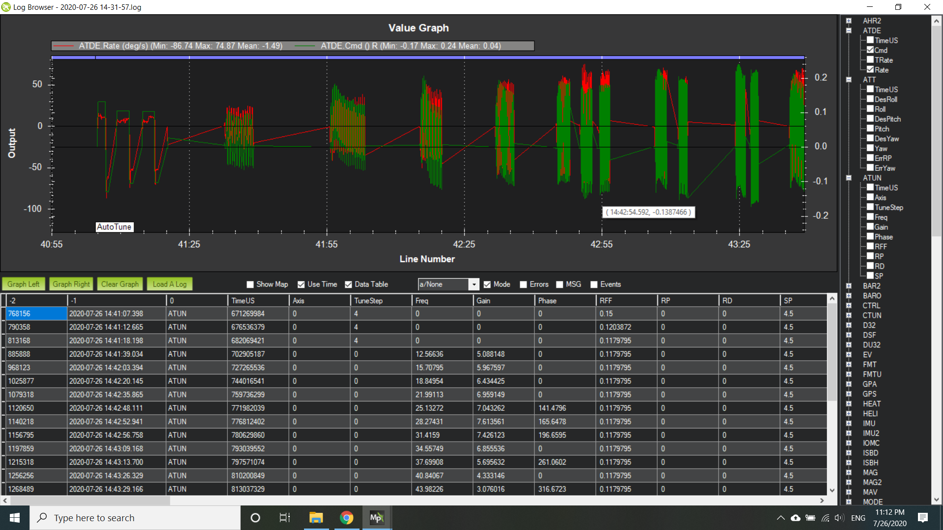
This is from a flight I peformed earlier today on my 600 size JR Ergo. I’ve plotted angular roll rate and the commanded roll output from the motors class (Rout). In less than 3 minutes, it performed the calculation of the FF gain and the sweep of dwells. The results of the dwells are listed below the graph. The frequency is in rad/s and the gain and phase is given. Given this data, the max allowable gain or the gain that would get you to within 6 db (safe margin) of the instability can be calculated for the rate P gain. It was determined to be 0.1 for rate P. I had previously tuned this aircraft about a year ago and had reached 0.07 before stopping because I started seeing feedback oscillations. My calculation did not match where I stopped my tuning because the safe margin of 6 db to the instability is not the right gain for a good tune. So my next step is to determine the step down from that calculation that gives a good tune.
Like I mentioned earlier, I figured out how to use this data to also determine the max allowable rate D gain. This uses the same data except, it is transformed in the frequency domain to a frequency response of angular acceleration to commanded input by multiplying the gain by the dwell frequency and subtracting 90 deg from the phase. The max allowable rate D gain was calculated to be 0.0035. Data from the tuning I did a year ago, showed that I went to 0.003 before stopping because of the feedback oscillations.
Plans forward with the autotune will be to package the dwell sweep into a separate test that will be conducted prior to Rate D and Rate P tuning. An appropriate knock down factor would be applied to the max allowable gains to come up with the rate P and rate D gains and then these gains would be tested in the rate P and rate D tests to verify the aircraft response is appropriately tuned and free of feedback oscillation.
9 Likes