No need to set FFT_ENABLE.
When you go to load the FFT graphs in MissionPlanner put a check mark in the “Magnitude” box at bottom left, then load the log - all will be much clearer!
That… well, what do you think?
With that on ACC0, there is a peak at about 96hz, one at about 112. Those appear to repeat much smaller at about 193 and 226. Then on GYRO0 I see essentially the same peaks? GYR3, they are there too, but much smaller and don’t seem to have much repetition.
I’m still like the dude with the double rainbows asking what does it mean…
As I said don’t bother with acceleration. This is what you are looking at:
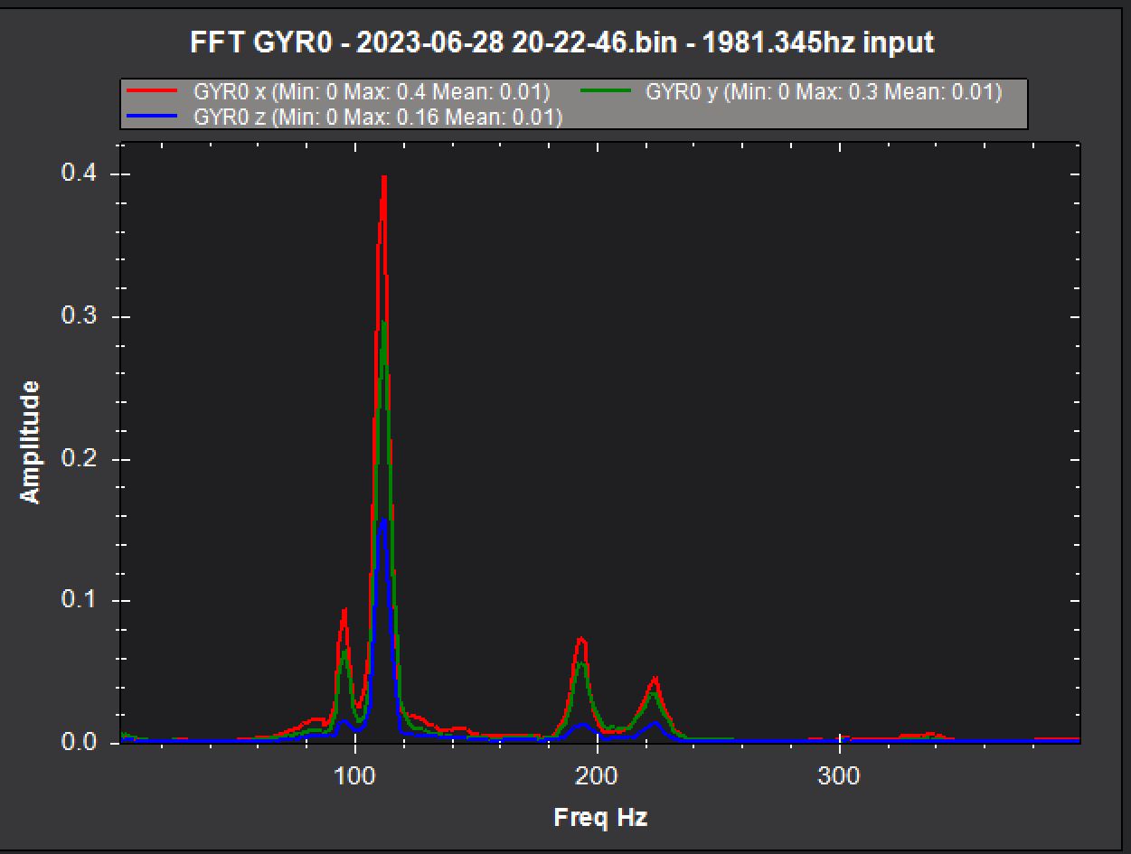
You could probably set the center frequency at 104Hz, BW at 1/2 of that and get them both plus the harmonics. Set the FM_RATE to 0.75
And as Shawn said disable FFT, it is doing nothing for you.
Why did you change the PID values? You were at a good starting point in the previous log you posted. Big step backward with even some default parameters in there now. All you needed to do was fix the yaw bias and configure the notch filter before moving on.
Yes, it can take a bit to come to terms with all this filter stuff.
You’ve still got the physical yaw bias that Dave spoke of. Maybe you can swap around some of the motor mounts or arm mounts to achieve less twisted motor mounts.
This is what gives you those double peaks of closely related frequencies.

Until the arm or motor mount twist is fixed, there will be trouble nailing down the harmonic notch filter. We’d have to set up two filters, which should probably be avoided.
The in-flight FFT is actually close to being correct. So that’s something…
Just set these for now:
FFT_ENABLE,0
INS_HNTCH_ENABLE,1
INS_HNTCH_MODE,1
INS_HNTCH_REF,0.2
INS_HNTCH_FREQ,90
INS_HNTCH_BW,40
INS_HNTCH_FM_RAT,0.7
INS_HNTCH_HMNCS,3
INS_HNTCH_OPTS,0
and that should be OK at least until you’ve done more test flights with the arms/motor mounts fixed.
So my goal right now is to stop tuning until I can get RCOUT 1-4 to all line up. If I can’t do that, then the rest of it is trash anyway.
I have backups and can roll back before I started experimenting with the rest of it. No worries.
I’ll sleep on it and come back tomorrow with some results. I just figured out that the label I stuck on it for the FAA (blue painters tape) got between the arm and the mount. Maybe that little bit was part of it being upset with me. I’ll go through the others and see what else I can find.
Thanks for all your help.
This is super frustrating. I did find that one motor mount wants to be able to wobble if I try to twist it. The others do not move at all. I sincerely believe I might have over-tightened this one. I’m going to punt - ordered a new frame and will see where that gets me. Expensive lesson but sadistically fun. In the end maybe I’ll be able to emerge victorious with two drones.
The good point is you’ll have spare parts available.
It seems my fiddling around has closed the gap a little bit, but I still have that mechanical yaw bias that shows up in the rcout chart. The model seems to be flying well even with this going on. My question is, do you think it is okay to use the drone to do some photography this weekend? What is the general risk involved? I don’t want to lose it to a crash or anything. Where I am going to be is just countryside with no houses or people, so I don’t anticipate putting anyone at undue risk or anything. Just curious if this will create a severe risk of wind gusts making it go haywire or not.
The only severe risk is if the bias is so high that under demand, say Pitch and/or Roll plus Yaw some outputs max out causing a loss of stability and authority. You will know that if thrust loss errors occur. If you are cruising along sedately taking video I suppose the risk of that is low. Plus you generally have good Thrust/weight with the average PWM output across the motors <1500us.
Just curious here @carltondhouston… did you order another hexsoon 450, and if so, how did it turn out? What do you think of the overall frame? Also, whats your take on the T-Motor 450II kit?
@Sanperez I can’t really give much of a review as the EDU-450v2 kit is the only frame with which I have experience. And if you read this thread you would know something of the trouble I have had producing a good quadcopter with it. The only reason I ordered a second kit was to try to work my way out of this annoying yaw bias issue. Furthermore, if I’d known I needed a second kit I never would have ordered the 450ii t-motor kit. AFAIK that kit has the exact same motors and ESC’s as the frame kit although the frame kit parts are rebranded and/or made to look completely generic. In both cases, the ESC’s are plain jane without blheli firmware.
I chose the EDU450v2 because of the teardrop arms. I like how the esc’s and wiring are inside those arms. I also had read about trouble people have had with other frames keeping motors perfectly aligned. While I think this frame helps with that in this part of the design, there are obviously ways to screw that up - so nothing is foolproof. But I think I can keep it straight now, so maybe it’ll be good.
It is intended to be a learning platform, and I think it does well for that. I like that Cube provides full STEP files for all their stuff including the EDU-450 parts, so you can create things to fit it perfectly in your favorite CAD. I suppose lots of manufacturers are getting into that, which is great, but this is the first place I encountered that tidbit myself.
Maybe someday I will build a somewhat larger flying thing, but for the most part I can get what I want done with this little stuff. I hope that mixed bag helps answer whatever question you had.
@dkemxr I received my new EDU-450 frame and have rebuilt my quad. The only stuff I used from the old frame was the electronic parts. I also started over with a reset to defaults. This afternoon I have gone through the very first parts of the tuning wiki and stopped to get your take on things.
Interestingly, I still see a difference in the RCOUT graphs between the CW and CCW motors. The point I stopped at was just setting the logging option for batch logging FFT information to get a view into the notch center frequency. That log looks better to my eye in that I see one spike and not two.
Oh, and I also upgraded to blheli_32 ESC’s. The motors spin all the way down to 1%, so I picked 2% and set parameters from there on MIN spin, etc. It’s nice being able to set motor direction without rewiring too. Following the docs, I put the motors on aux ports, so they’re at 10-13 instead of 1-4 because of the passthrough thing with the cube orange+.
Anyway, here’s the log:
I’m hoping you can help me ease into a descent tune or if that yaw bias is really as bad as I think it is. If it is, I might have to find something else to do for a while. haha.
It’s there but not terrible. You should be using the Bdshot version of firmware now that you have proper ESC’s. Flash that and set the appropriate parameters to enable it for motor RPM.
Also, these are at default, fix that:
ATC_ACCEL_P_MAX,110000
ATC_ACCEL_R_MAX,110000
ATC_ACCEL_Y_MAX,27000
And set this:
INS_LOG_BAT_OPT,4
Looks like you have lost some thrust for some reason. Hover thrust is ~0.35 now. If that stays consistent change the PSC_ACCZ_P&I parameters accordingly.
Configure the Notch filter for ESC RPM and then run Auto Tune.
I just put together the whole bi-directional dshot for motor RPM. I’m working through that now, I just need to figure out how to see if I am getting the data back or not. Related question I had was whether or not I should consider adding a capacitor to these or not. There are pads for that which are marked, but I didn’t buy any to put on them. Do you have a recommendation there?
I got a little bit confused on the ATC_ACCEL_P/R/Y_MAX params. They get set with the initial params wizard, but the doc page prescribes different values for them, which is why I set them to those other values (the 110000, and 27000). So I re-ran the wizard and unchecked all but those values. ATC_ACCEL_Y_MAX is still at 27000. What’s the right way to set those?
Lost thrust is interesting. I wonder if the Hexsoon branded 2212/920KV motors are less efficient than the T-Motor branded 2212/920KV motors… or if these ESC’s in combination produce less thrust. I’ll keep an eye on MOT_THST_HOVER as it learns.
From the Initial Tune Parameters.
Just be aware the Initial Parameters Calc in MissionPlanner does NOT read in your existing values first!
You have to enter your prop size and battery details, THEN when you press “Calculate” you get the table comparing what you have now and what the new changes will be, giving you the opportunity to be selective.
Some people assume when the wizard is first run it has already read your existing params and they appear “wrong”
Thanks. I have been keeping copies of the params at various stages and doing diffs as I’ve changed things, including the initial setup wizard. I think I’ve been able to stay between the ditches with it.
I got motor RPM from the ESC’s using bi-directional dshot. How do I enable harmonic notch to run against that RPM data? Is it as simple as enabling INS_HNTCH_ENABLE and setting MODE to 3?
That information is great. My question was asked after having gone through it. I’ll go through it again. Thanks so much for the link.
Probably this:
INS_HNTCH_ENABLE,1  // write then refresh params to see the rest
INS_HNTCH_FM_RAT,1.0
INS_HNTCH_HMNCS,3
INS_HNTCH_MODE,3
INS_HNTCH_REF,1
And ensure you also have
INS_LOG_BAT_MASK,1
INS_LOG_BAT_OPT,4